Convenient dust removal device

A dust-removing device and a convenient technology, which can be used in spraying devices, liquid spraying devices, mixers with rotary stirring devices, etc., can solve the problems of uneven mixing of water and solvent, expensive spraying equipment, low efficiency of manual watering, etc. It is convenient for moving and handling work, convenient for spraying work, and the effect of quick disassembly and assembly work.

CN108114553AInactive Publication Date: 2018-06-05广西南宁东能建筑工程技术有限公司
0 Cites 0 Cited by

Patent Information

Authority / Receiving Office
CN · China
Patent Type
Applications(China)
Current Assignee / Owner
Publication Date
2018-06-05
Estimated Expiration
Not applicable · inactive patent

Smart Images

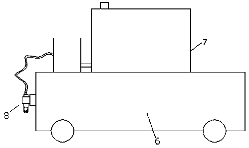
  • Figure 1
    Figure 1
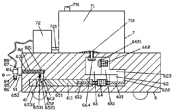
  • Figure 2
    Figure 2
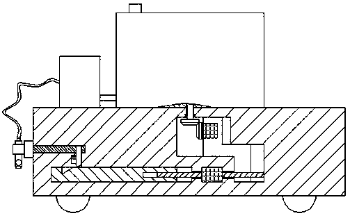
  • Figure 3
    Figure 3
Patent Text Reader

Abstract

The invention discloses a convenient dust removal device. The convenient dust removal device comprises an atomizing seat body, an atomizing device and an atomizing frame device, wherein the atomizingdevice is arranged at the top of the atomizing seat body, and the atomizing frame device is mounted on the left side surface of the atomizing seat body; and the atomizing device comprises a water cylinder and an atomizing pump, a stirring shaft extending downwards is cooperatively and rotatably connected in the water cylinder, a first sliding conveying cavity is formed in the atomizing seat body below the air cylinder, the tail of the bottom of the stirring shaft stretches into the first sliding conveying cavity, a first cone-shaped wheel is fixedly arranged at the tail, a first sliding conveying block is cooperatively connected in the first sliding conveying cavity on the right side of the first cone-shaped wheel, a first motor is arranged in a left side surface on the upper side of the first sliding conveying block, a second cone-shaped wheel which stretches outside the left side surface of the first sliding conveying block and is cooperatively connected with the first cone-shaped wheel is cooperatively connected to the left side of the first motor, and a second motor is arranged in the atomizing seat body below the first sliding conveying cavity. The convenient dust removal device is simple in structure and convenient to operate, dismount, mount, move, carry and maintain, the time and the labor are saved, the uniform stirring is realized, and the working efficiency is improved.
Need to check novelty before this filing date? Find Prior Art

Description

technical field

[0001] The invention relates to the technical field of dust removal, and relates to a convenient dust removal device. Background technique

[0002] In construction sites and other places, due to the large amount of dust generated during construction, the dust passing through the workers' respiratory tract will seriously affect the health of the workers' lungs. Some artificial sprinkling is inefficient, time-consuming and laborious, and some spraying equipment is expensive and complex in structure. The spray racks on the spraying device are generally fixed as a whole, and cannot be unfolded or folded. Sometimes it is necessary to add a solvent to the water to achieve a specific effect, but the existing spray device adopts a manual mixing method, which makes the mixing of the water and the solvent uneven. Contents of the invention

[0003] The technical problem to be solved by the present invention is to provide a convenient dust removal device, which can so...

Examples

Embodiment Construction

[0021] Such as Figure 1-Figure 6 As shown, a convenient dust removal device of the present invention includes a spray seat body 6 and a spray device 7 arranged on the top of the spray seat body 6 and a spray rack device 8 installed on the left side of the spray seat body 6 , the spray device 7 is composed of a water tank 71 and a spray pump 72, the mixing shaft 710 extending downward is connected to the inside of the water tank 71, and the spray seat 6 below the water tank 71 is equipped with There is a first sliding chamber 66, the bottom end of the mixing shaft 710 extends into the first sliding chamber 66 and the end is fixed with a first conical wheel 664, the right side of the first conical wheel 664 Sliding in the first sliding chamber 66 is connected with a first sliding block 661, the left side of the upper side of the first sliding block 661 is provided with a first motor 662, and the left side of the first motor 662 fits A second conical wheel 6621 extending to the...