Biomass particle processing equipment in new energy field

A technology for biomass particles and processing equipment, which is applied in the cleaning method using tools, the cleaning method using gas flow, and solid separation, etc., can solve the problems of unreliability, affecting the working environment, and low dust removal quality, so as to improve the use efficiency. , The effect of increasing the contact area and improving the feeding speed

Inactive Publication Date: 2018-06-19
DONGGUAN XIANGFEI INTELLIGENT EQUIP TECH CO LTD
View PDF0 Cites 6 Cited by
  • Summary
  • Abstract
  • Description
  • Claims
  • Application Information

AI Technical Summary

Problems solved by technology

Generally speaking, biomass is added to biomass particles before use, but in the process of biomass production or in the process of transportation and storage, the formed biomass particles will be contaminated with dust, which seriously affects the use of biomass particles Effect
Most of the existing biomass particle processing equipment removes dust by scraping with brushes over and over again, which not only has poor dust removal effect, but also has low dust removal efficiency
During the dust removal process, not only will the biomass particles be severely scratched, affecting the use of biomass, but also the quality of dust removal is low
And after the dust removal, the dust in the biomass particles is not effectively screened out. When collecting materials, not only the dust storms, but also affect the working environment and pollute the air environment
Moreover, effective screening cannot be carried out, and other equipment is needed to assist in screening. The use efficiency is low, and it is very impractical and unreliable.

Method used


Image

  • Biomass particle processing equipment in new energy field
  • Biomass particle processing equipment in new energy field
  • Biomass particle processing equipment in new energy field

Examples


Embodiment Construction

[0027] Below in conjunction with accompanying drawing and specific embodiment the present invention is described in further detail:

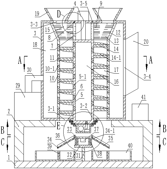
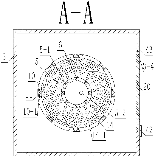
[0028] Such as Figure 1-Figure 7As shown, a biomass particle processing equipment in the new energy field includes a base plate 1, an L-shaped support frame 2 is symmetrically fixed on the top surface of the base plate 1, and a box body is fixed on the top surface of the L-shaped support frame 2 3. The central part of the bottom surface of the box body 3 is provided with a through hole A3-2, the top surface of the box body 3 is fixed with a motor 4, the driving end of the motor 4 penetrates into the box body 3, and the driving end of the motor 4 A cylinder 5 is fixedly connected, and the bottom of the cylinder 5 is slidably connected with the through hole A3-2. A cavity A16 is formed inside the cylinder 5, and a plurality of through holes B5-1 are uniformly arranged on the cylinder 5. A filter screen A6 is fixed in the through hole B5-1, an an...


PUM


Abstract

The invention discloses biomass particle processing equipment in the new energy field. The biomass particle processing equipment comprises a bottom plate. L-shaped supporting frames are symmetricallyfixed to the top face of the bottom plate. A box body is fixed to the top faces of the L-shaped supporting frames. A through hole A is formed in the center of the bottom face of the box body. A motoris fixed to the top face of the box body. The driving end of the motor penetrates into the box body. A barrel is fixedly connected with the driving end of the motor. The bottom of the barrel is slidably connected with the through hole A. A cavity A is formed in the barrel. A plurality of through holes B are evenly formed in the barrel. Filtering screens A are fixed in the through holes B. An annular groove is formed in the top face of the inner wall of the box body. An annular rod matched with the annular groove is slidably arranged in the annular groove. A sleeve A is fixed to the top face ofthe barrel. The top face of the sleeve A is fixed to the bottom face of the annular rod. Through the biomass particle processing equipment, biomass particles can be dedusted, in addition, the dedusting efficiency is high, the dedusting quality is good, dust in the particles can be screened out, the using efficiency of the biomass particles is improved, the material collection speed is high, and the biomass particle processing equipment is quite practical and reliable.

Description

technical field [0001] The invention relates to the field of new energy, in particular to biomass particle processing equipment in the field of new energy. Background technique [0002] Biomass energy refers to the use of natural plants, manure, and urban and rural organic waste to convert photosynthetic energy into photosynthesis, which is a very good renewable energy source. Generally speaking, biomass is added to biomass particles before use, but in the process of biomass production or in the process of transportation and storage, the formed biomass particles will be contaminated with dust, which seriously affects the use of biomass particles Effect. Most of the existing biomass particle processing equipment removes dust by scraping with brushes over and over again, which not only has poor dust removal effect, but also has low dust removal efficiency. During the dust removal process, not only will the biomass particles be severely scratched, affecting the use of biomass...

Claims


Application Information

Patent Timeline
Patent Type & Authority Applications(China)
IPC IPC(8): B08B1/02B08B5/02B08B13/00B07B1/28
CPCB08B1/002B07B1/28B08B1/02B08B5/023B08B13/00
Inventor 邓凯谢海燕廖慧
Owner DONGGUAN XIANGFEI INTELLIGENT EQUIP TECH CO LTD
Why Eureka
Try Eureka