Device for testing wear resistance of rubber material

A testing device and technology of rubber materials, applied in the direction of testing wear resistance, etc., can solve the problems of poor testing effect, high labor intensity, dust affecting the surrounding environment, etc.

Active Publication Date: 2018-07-20
安徽创园体育科技有限公司
View PDF14 Cites 8 Cited by
  • Summary
  • Abstract
  • Description
  • Claims
  • Application Information

AI Technical Summary

Problems solved by technology

[0005] In order to overcome the disadvantages of poor test effect, high labor intensity and easy occurrence of a large amount of dust affecting the surrounding environment in the test process when manually testing the wear resistance of rubber materials, the technical problem to be solved by the present invention is to provide a test effect Excellent, low labor intensity, can suck away the dust that appears during the test, without affecting the surrounding environment

Method used


Image

  • Device for testing wear resistance of rubber material
  • Device for testing wear resistance of rubber material
  • Device for testing wear resistance of rubber material

Examples


Embodiment 1

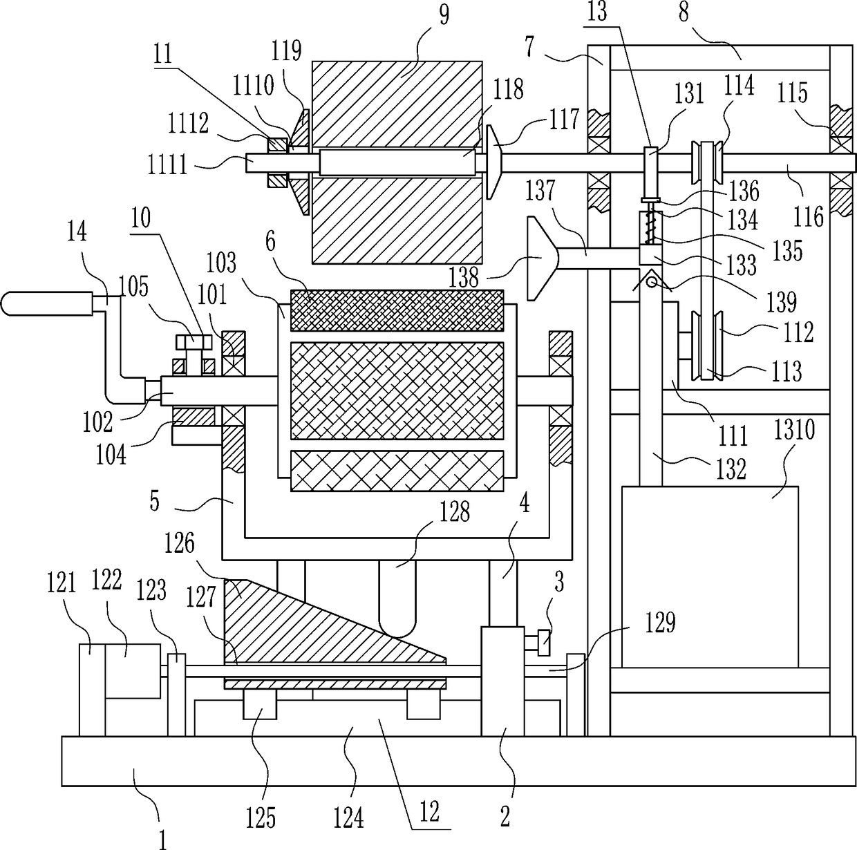
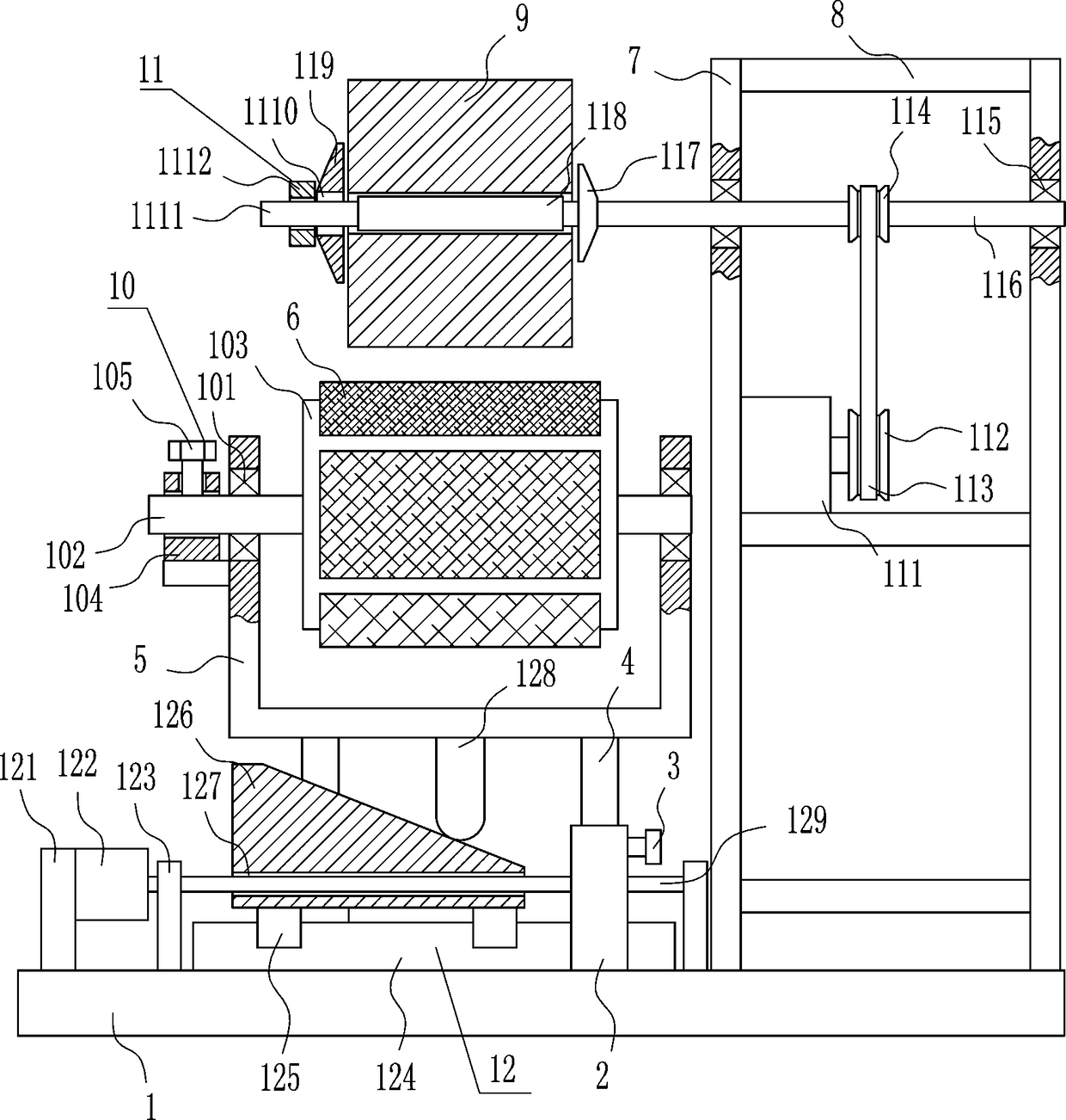
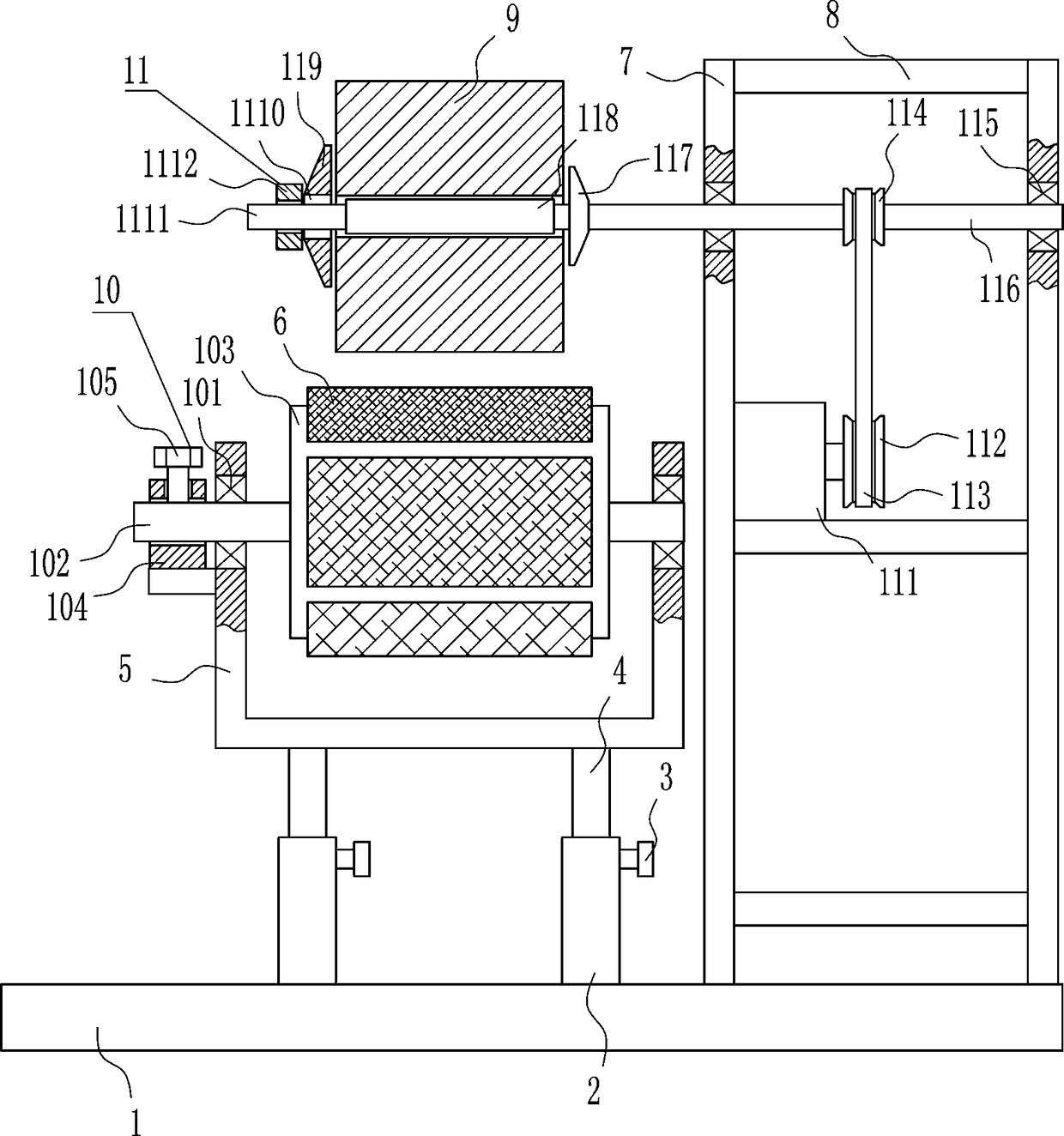
[0031] A device for testing the abrasion resistance of rubber materials, such as Figure 1-5 As shown, it includes a base plate 1, a sleeve 2, a first fastening bolt 3, a movable rod 4, a frame 5, a friction plate 6, a vertical plate 7, a horizontal plate 8, an adjusting device 10 and a rotating device 11, and the top of the base plate 1 is left and right Sleeve 2 is installed on both sides, a movable rod 4 is arranged inside the sleeve 2, and a first fastening bolt 3 is arranged on the upper right side of the sleeve 2, and the first fastening bolt 3 is in contact with the movable rod 4, and the left and right sides move A frame 5 is installed between the top ends of the rods 4, and an adjustment device 10 is provided on the frame 5, and friction plates 6 with different roughness are connected to the adjustment device 10, and vertical boards 7 and vertical boards 7 are symmetrically installed on the right side of the top of the bottom board 1 Located on the right side of the r...

Embodiment 2

[0033] A device for testing the abrasion resistance of rubber materials, such as Figure 1-5 As shown, it includes a base plate 1, a sleeve 2, a first fastening bolt 3, a movable rod 4, a frame 5, a friction plate 6, a vertical plate 7, a horizontal plate 8, an adjusting device 10 and a rotating device 11, and the top of the base plate 1 is left and right Sleeve 2 is installed on both sides, a movable rod 4 is arranged inside the sleeve 2, and a first fastening bolt 3 is arranged on the upper right side of the sleeve 2, and the first fastening bolt 3 is in contact with the movable rod 4, and the left and right sides move A frame 5 is installed between the top ends of the rods 4, and an adjustment device 10 is provided on the frame 5, and friction plates 6 with different roughness are connected to the adjustment device 10, and vertical boards 7 and vertical boards 7 are symmetrically installed on the right side of the top of the bottom board 1 Located on the right side of the r...

Embodiment 3

[0036] A device for testing the abrasion resistance of rubber materials, such as Figure 1-5 As shown, it includes a base plate 1, a sleeve 2, a first fastening bolt 3, a movable rod 4, a frame 5, a friction plate 6, a vertical plate 7, a horizontal plate 8, an adjusting device 10 and a rotating device 11, and the top of the base plate 1 is left and right Sleeve 2 is installed on both sides, a movable rod 4 is arranged inside the sleeve 2, and a first fastening bolt 3 is arranged on the upper right side of the sleeve 2, and the first fastening bolt 3 is in contact with the movable rod 4, and the left and right sides move A frame 5 is installed between the top ends of the rods 4, and an adjustment device 10 is provided on the frame 5, and friction plates 6 with different roughness are connected to the adjustment device 10, and vertical boards 7 and vertical boards 7 are symmetrically installed on the right side of the top of the bottom board 1 Located on the right side of the r...


PUM


Abstract

The invention relates to a test device, in particular, a device for testing the wear resistance of a rubber material. The invention aims to provide a test device, which is used to test the wear resistance of a rubber material, has the advantages of good testing effect and low labor strength, can absorb dusts during the testing process, and does not influence the surrounding environment. The invention provides a device for testing the wear resistance of a rubber material. The device comprises a bottom plate, sleeves, first fastening bolts, and movable rods. The left side and right side of the top of the bottom plate are both provided with a sleeve. A movable rod is arranged in each sleeve. The upper part of the right side of each sleeve is provided with a first fastening bolt. The first fastening bolts contact with the movable rods. A frame is arranged between the top end of the left movable rod and the top end of the right movable rod. By driving the device, people do not need to pullthe frame to contact a friction plate with a rubber material, time and labor are saved, the testing effect is good, the labor strength is low, during the testing process, the dusts can be absorbed, and surrounding environment is not influenced.

Description

technical field [0001] The invention relates to a testing device, in particular to a rubber material abrasion resistance testing device. Background technique [0002] Rubber refers to a highly elastic polymer material with reversible deformation. It is elastic at room temperature, can produce large deformation under a small external force, and can return to its original shape after the external force is removed. Rubber is a completely amorphous polymer with a low glass transition temperature and often a large molecular weight, greater than hundreds of thousands. [0003] Before the rubber material is produced, the rubber material sample will be tested for wear resistance first, so that the rubber material will have a better effect in subsequent use. However, when the rubber material is manually tested for wear resistance, the test effect is not good and the labor intensity is high. , a large amount of dust is likely to appear during the test and affect the surrounding envir...

Claims


Application Information

Patent Timeline
Patent Type & Authority Applications(China)
IPC IPC(8): G01N3/56
CPCG01N3/56
Inventor 陈雅凌征强杨楠衷小聪
Owner 安徽创园体育科技有限公司
Why Eureka
Try Eureka