Overflow weir and elastic force type stilling pool combined energy dissipation structure and energy dissipation method

A technology for stilling tanks and overflow weirs, applied in barrage/weirs, water conservancy projects, sea area projects, etc., can solve problems such as low energy dissipation efficiency of stilling tanks, excessive pressure on the bottom plate of stilling tanks, etc., and achieve improvement Atomization phenomenon, reduce dynamic water pressure, increase the effect of buffering effect

Active Publication Date: 2018-09-11
KUNMING UNIV OF SCI & TECH
View PDF4 Cites 2 Cited by
  • Summary
  • Abstract
  • Description
  • Claims
  • Application Information

AI Technical Summary

Problems solved by technology

[0007] Aiming at the deficiencies of air entrainment in the discharge and energy dissipation design of hydraulic structures, the low energy dissipation efficiency of the stilling basin and the excessive pressure on the bottom plate of the stilling basin, the present invention provides an overflow weir and an elastic energy dissipation unit. Combined Energy Dissipation Structure and Energy Dissipation Method of Force Pool

Method used


Image

  • Overflow weir and elastic force type stilling pool combined energy dissipation structure and energy dissipation method
  • Overflow weir and elastic force type stilling pool combined energy dissipation structure and energy dissipation method
  • Overflow weir and elastic force type stilling pool combined energy dissipation structure and energy dissipation method

Examples


Embodiment 1

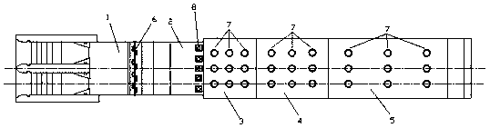
[0038] Embodiment 1: as Figure 1~12 As shown, the combined energy dissipation structure of the overflow weir and the elastic stilling tank includes the overflow weir and the stilling tank. The overflow weir includes a WES straight section 1 and a WES reverse arc section 2. The WES straight section 1 It is connected with the WES anti-arc section 2, and a rotating shaft component 6 is provided at the connection. The bottom of the tail of the WES anti-arc section 2 is provided with a hydraulic jacking device 8, and the tail of the overflow weir WES anti-arc section 2 Connected with the stilling pool, the stilling pool includes the head part 3 of the stilling pool, the middle part 4 of the stilling pool and the tail part 5 of the stilling pool. 3 connection, the bottom of the stilling pool is installed with rubber bearings according to the pressure it bears, because the pressure on the head 3 of the stilling pool is relatively large, which is about 1.5 times that of the middle pa...

Embodiment 2

[0045] Embodiment 2: The structure of this embodiment is the same as that of Embodiment 1. The difference is that rubber bearings are installed at the bottom of the stilling pool according to the pressure it bears. 1.5 times that of the middle part 4 of the stilling pool, so the density of rubber bearings under the bottom plate of the head 3 of the stilling pool is 25㎡ / piece; while the pressure on the middle part 4 of the stilling pool is about 1.3 of the pressure at the tail 5 of the stilling pool times, so the density of the rubber bearings under the bottom plate is 37.5㎡ / piece; for the pressure at the end 5 of the stilling pool, the density of the rubber bearings under the bottom plate of the stilling pool’s tail 5 is 50㎡ / time, the effect achieved is ideal.

[0046] This embodiment is mainly used for single-width flow at 170m 3 / s·m~195m 3 / s·m for energy dissipation, adjust the hydraulic pump 8-1 of the hydraulic jacking device 8 to lower the hydraulic pump 8-1, thereb...

Embodiment 3

[0048] Embodiment 3: The structure of this embodiment is the same as that of Embodiment 1. The difference is that rubber bearings are installed at the bottom of the stilling tank according to the pressure it bears. In this embodiment, the overall pressure of the stilling tank generally increases , so the density of the overall rubber support of the stilling pool should be increased accordingly. Because the pressure on the head 3 of the stilling pool is relatively large, which is about 1.5 times that of the middle part 4 of the stilling pool, so for the head 3 of the stilling pool The density of rubber bearings under the bottom plate is 30㎡ / piece; while the pressure in the middle part 4 of the stilling pool is about 1.3 times the pressure at the end of the stilling pool 5, so the density of rubber bearings under the bottom plate is 45㎡ / piece; for the pressure borne by the tail part 5 of the stilling pool, when the density of rubber bearings installed under the bottom plate of ...


PUM


Abstract

The invention discloses an overflow weir and elastic force type stilling pool combined energy dissipation structure and an energy dissipation method. The overflow weir and elastic force type stillingpool combined energy dissipation structure comprises an overflow weir and a stilling pool, the overflow weir comprises a WES straight line section and a WES ogee section, the WES straight line sectionis connected to the WES ogee section, a rotating shaft part is arranged at the joint, a hydraulic jacking device is arranged at the bottom of the tail part of the WES ogee section, the tail part of the WES ogee section of the overflow weir is connected to the stilling pool, the stilling pool comprises a stilling pool head part, a stilling pool middle part and a stilling pool tail part, the tail part of the WES ogee section of the overflow weir is connected to the stilling pool head part, and more than one rubber support is arranged under a base plate of each of the stilling pool head part, the stilling pool middle part and the stilling pool tail part. According to the overflow weir and elastic force type stilling pool combined energy dissipation structure and the energy dissipation method, the ascending height of the hydraulic jacking device is adjusted, so that the height difference between the WES ogee section of the overflow weir and the stilling pool head part can be adjusted, thepurpose of energy dissipation can be achieved, and in the pouring process, the rubber support are arranged under the base plate of each of the stilling pool head part, the stilling pool middle part and the stilling pool tail part, so that energy dissipation can also be carried out.

Description

technical field [0001] The invention relates to a combined energy dissipation structure and energy dissipation method of an overflow weir and an elastic stilling basin, belonging to the field of flood discharge and energy dissipation of hydraulic structures in water conservancy and hydropower projects. Background technique [0002] In the design of dam engineering, flood discharge and energy dissipation are the two major tasks undertaken by the discharge structure, that is, to safely discharge excess flood water while strictly controlling the erosion of the dam body and downstream foundation pit by the discharge flow to prevent damage to the dam body and instability of the dam foundation . Especially for flood discharge projects with high water head and large flow, there are problems such as large flow velocity and pulsating pressure at the bottom of the bottom plate, high difficulty in anti-shock protection, large size of stilling basin required, and high cost. Therefore, r...

Claims


Application Information

Patent Timeline
Patent Type & Authority Applications(China)
IPC IPC(8): E02B8/06
CPCE02B8/06
Inventor 杨具瑞汤建青郭莹莹张勤洪美玲
Owner KUNMING UNIV OF SCI & TECH
Why Eureka
Try Eureka