
A Realization Method and Vibration Absorber Based on Hardened Cubic Stiffness
A cubic rigidity and realization method technology, applied in the direction of transmission, belt/chain/gear, inertial force compensation, etc., to achieve the effects of saving space, high reliability, and easy measurement
- Summary
- Abstract
- Description
- Claims
- Application Information
AI Technical Summary
Problems solved by technology
Method used
Image

Examples
Embodiment Construction
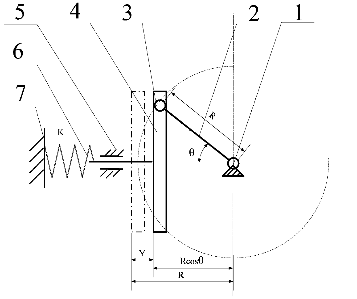
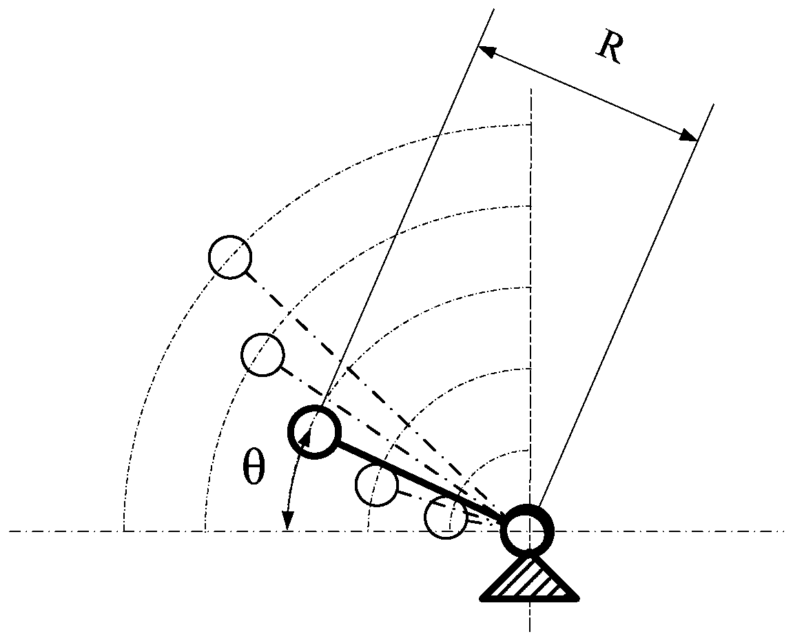
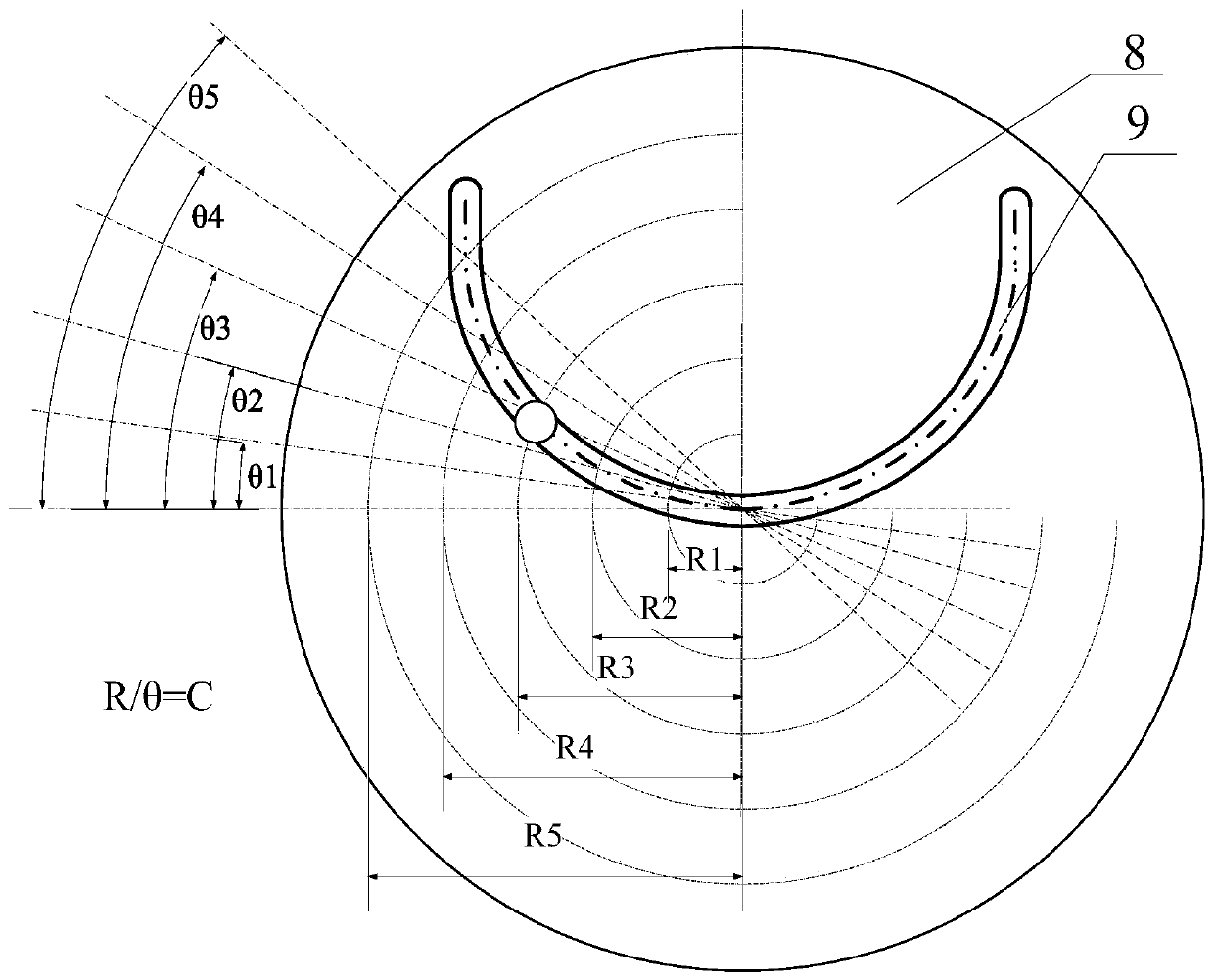
[0023] The present invention will be further described below in conjunction with the accompanying drawings. Such as figure 1 As shown, the main structure of the present invention is a sinusoidal mechanism, including a support 1, a rocking bar 2, a roller 3, a slider 4, a sliding guide rail 5, an elastic element 6 and a spring support 7; the rocking bar 2 is an input end, and the The bracket 1 rotates, the rocker 2 drives the slider 4 to move linearly through the roller 3 , and the slider 4 is connected with the spring support 7 through the elastic element 6 . The slider 4 is restricted by the sliding track 5 to move in a straight line parallel to it. There is an inner track perpendicular to the movement direction inside the slider 4. The sliding track 5 and the rotation center of the rocker 2 are on a straight line. When the rocker 2 swings at a certain angle θ , the roller 3 at the end of the rocker will push the slider through the inner track of the slider 4 to make a linea...
PUM
 Abstract
Description
Claims
Application Information