Thermal type vortex shedding flow metering device, flowmeter and flow measurement method of vortex shedding flow metering device

A vortex flow, metering device technology, applied in the measurement flow/mass flow, measurement device, liquid/fluid solid measurement and other directions, can solve the problems of high requirements, lack of installation conditions, affecting the measurement accuracy of the flowmeter, etc Accurate measurement results, sensitive to thermal energy changes, and improved accuracy

Pending Publication Date: 2018-10-19
GOLDCARD HIGH TECH
View PDF8 Cites 2 Cited by
  • Summary
  • Abstract
  • Description
  • Claims
  • Application Information

AI Technical Summary

Problems solved by technology

[0004] 1. The range of the traditional vortex flowmeter is 1:20, in which the piezoelectric crystal is used as the sensor. During the measurement of the vortex frequency by the piezoelectric crystal, if the flow velocity of the fluid is less than 5m / s and the flow rate is too small, after The vortex of the sensor is so small that it is difficult to capture, and the traditional vortex flowmeter cannot be measured
[0005] 2. The traditional vortex flowmeter has high requirements on the straight pipe upstream of the flowmeter during installation, and the installation conditions may not be met during installation, which limits the application of the vortex flowmeter in many occasions
[0006] 3. The sensor in the vortex flowmeter is fixedly installed downstream of the columnar vortex generator. When the measuring pipeline vibrates axially along the pipeline, the sensor in the pipeline will move relative to the fluid in the pipeline driven by the pipeline. At this time, the piezoelectric crystal will misjudge the relative motion as a flow signal, which will affect the measurement accuracy of the flowmeter.

Method used


Image

  • Thermal type vortex shedding flow metering device, flowmeter and flow measurement method of vortex shedding flow metering device
  • Thermal type vortex shedding flow metering device, flowmeter and flow measurement method of vortex shedding flow metering device
  • Thermal type vortex shedding flow metering device, flowmeter and flow measurement method of vortex shedding flow metering device

Examples


Embodiment Construction

[0030] The present invention will be further described below in conjunction with the accompanying drawings.

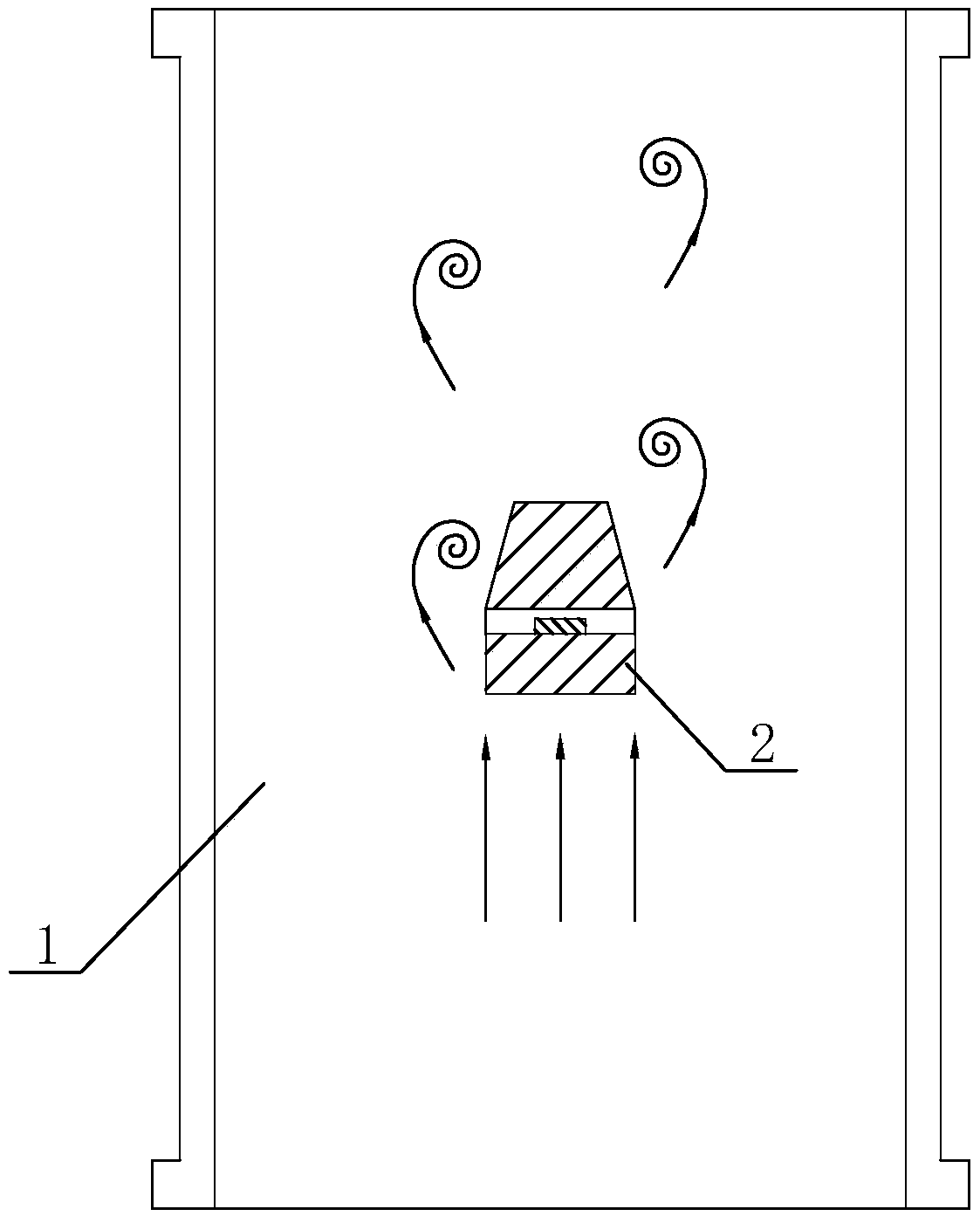
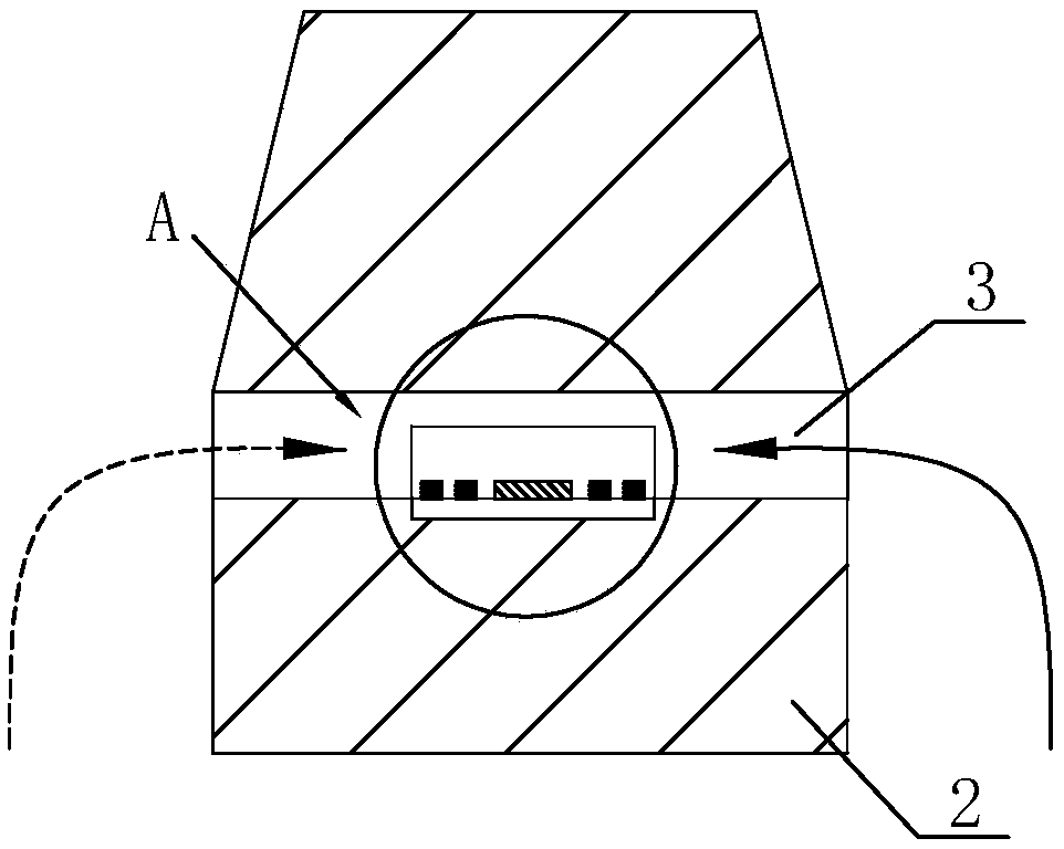
[0031] figure 1 It is a schematic cross-sectional structure diagram of a thermal vortex flow metering device. The vortex flowmeter in this embodiment includes the above-mentioned flowmeter body and the thermal vortex flow metering device. figure 1 The direction of the middle arrow is the direction of fluid flow. The small flow fluid flows into the measuring pipeline 1 from the upstream inlet of the measuring pipeline 1 of the flowmeter. In the middle of the measuring pipeline 1, there is a vortex generator 2 that makes the airflow generate a regular staggered vortex street. The vortex generating body 2 is a cylindrical vortex generating body 2 , the cross section of the vortex generating body 2 is triangular or trapezoidal, and the vortex generating body 2 is arranged on the diameter line of the circular cross section of the measuring pipeline 1 . The fluid with a s...


PUM


Abstract

The invention discloses a thermal type vortex shedding flow metering device, a flowmeter and a flow measurement method of the vortex shedding flow metering device. The vortex shedding flow metering device includes a measuring pipeline and further includes a vortex generator used for making fluid generate regular vortexes. The generator is located in the measuring pipeline, a fluid channel used forthe fluid passing through is arranged on the vortex generator, the fluid channel is internally provided with a sensor used for detecting the vortex frequency, and the sensor refers to a thermoelectric sensor. The invention further discloses the vortex shedding flowmeter provided with the thermal type vortex shedding flow metering device. The invention provides the flow metering device high in anti-interference ability and the flow measurement method of the flow metering device. By detecting regular temperature variation caused by vortex signals, temperature and pressure modification is not needed when the flowmeter is installed, the installation time is shortened, and the flowmeter is suitable for more installation sites.

Description

technical field [0001] The invention relates to the field of flow measurement, in particular to a thermal vortex flow metering device, a flow meter and a flow measurement method thereof. Background technique [0002] The vortex flowmeter is a volume flowmeter that measures the volume flow of gas, steam or liquid, the volume flow of standard conditions or the mass flow based on the research and production of Karman (Karman) vortex street principle. It is mainly used for flow measurement of industrial pipeline media fluids, such as gas, liquid, steam and other media. [0003] Figure 4 The basic schematic diagram of the vortex flowmeter is shown, as attached Figure 4 The vortex generator shown in is located in the middle of the measuring pipe 1, the fluid flows through the vortex generating body 2, and regular vortices are alternately generated on both sides of the vortex generating body 2, and the frequency of the vortex is proportional to the flow velocity of the fluid. Th...

Claims


Application Information

Patent Timeline
Patent Type & Authority Applications(China)
IPC IPC(8): G01F1/32
CPCG01F1/32G01F1/325
Inventor 钭伟明丁渊明项勇陈红郑水云
Owner GOLDCARD HIGH TECH
Why Eureka
Try Eureka