A liquid crystal phase shifter and its manufacturing method, liquid crystal phase shifter and antenna

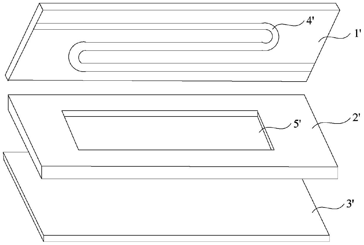
A production method and liquid crystal technology, applied in the field of phase shifting, can solve the problems of large fluctuation of liquid crystal molecule filling volume, uneven thickness of liquid crystal cell 5', poor cell thickness uniformity, etc., so as to avoid the influence of microwave signal transmission and reduce Variation in box thickness and the effect of improving thickness uniformity

Active Publication Date: 2020-06-26
CHENGDU TIANMA MICROELECTRONICS
View PDF6 Cites 0 Cited by
  • Summary
  • Abstract
  • Description
  • Claims
  • Application Information

AI Technical Summary

Problems solved by technology

[0004] Because the cell thickness of the current liquid crystal phase shifting unit is relatively large, which can reach hundreds of microns, and based on the structure of the existing liquid crystal phase shifting unit, on the one hand, when the liquid crystal tank 5' is set in the second rigid substrate 2', There will inevitably be process errors, resulting in uneven thickness of the liquid crystal tank 5', which in turn leads to poor cell thickness uniformity and large fluctuations in the filling volume of liquid crystal molecules; on the other hand, this structure cannot realize the liquid crystal tank 5'. The corresponding area is effectively supported, which further leads to the problem of uneven box thickness

Method used


Image

  • A liquid crystal phase shifter and its manufacturing method, liquid crystal phase shifter and antenna
  • A liquid crystal phase shifter and its manufacturing method, liquid crystal phase shifter and antenna
  • A liquid crystal phase shifter and its manufacturing method, liquid crystal phase shifter and antenna

Examples


Embodiment Construction

[0036] In order to better understand the technical solutions of the present invention, the embodiments of the present invention will be described in detail below in conjunction with the accompanying drawings.

[0037] It should be clear that the described embodiments are only some of the embodiments of the present invention, not all of them. Based on the embodiments of the present invention, all other embodiments obtained by persons of ordinary skill in the art without creative efforts fall within the protection scope of the present invention.

[0038] Terms used in the embodiments of the present invention are only for the purpose of describing specific embodiments, and are not intended to limit the present invention. As used in the embodiments of the present invention and the appended claims, the singular forms "a", "said" and "the" are also intended to include the plural forms unless the context clearly indicates otherwise.

[0039] It should be understood that the term "an...


PUM


Abstract

Embodiments of the present invention provide a liquid crystal phase shifting unit and a manufacturing method thereof, a liquid crystal phase shifter, and an antenna, which relate to the field of phase shifting technology. A support structure is used to achieve stable support for the liquid crystal filling area, which improves the uniformity of the cell thickness, and improves The transmission stability of the microwave signal is improved. The liquid crystal phase shifting unit includes: a first substrate and a second substrate oppositely arranged, and the area between the first substrate and the second substrate includes a liquid crystal filling area; a microstrip line, and the microstrip line is arranged on the first substrate towards the second substrate. On the surface, the orthographic projection of the microstrip line on the first substrate is located in the liquid crystal filling area; the supporting structure, the supporting structure is arranged between the first substrate and the second substrate, the supporting structure is located in the liquid crystal filling area, and the supporting structure is in the first The orthographic projection on the substrate does not overlap with the microstrip line; the liquid crystal molecules are filled in the liquid crystal filling area. The liquid crystal phase shifting unit is used for phase shifting the microwave signal.

Description

【Technical field】 [0001] The invention relates to the technical field of phase shifting, in particular to a liquid crystal phase shifting unit and a manufacturing method thereof, a liquid crystal phase shifter and an antenna. 【Background technique】 [0002] A phase shifter is a device that can adjust the phase of a wave. It is widely used in radar, accelerator, communication, instrumentation, and even music. Currently, the most widely used phase shifter is a liquid crystal phase shifter. [0003] The liquid crystal phase shifter includes multiple liquid crystal phase shifting units, such as figure 1 as shown, figure 1 It is a structural schematic diagram of a liquid crystal phase shifting unit in the prior art. The liquid crystal phase shifting unit includes a first rigid substrate 1', a second rigid substrate 2' and a third rigid substrate 3' which are oppositely arranged, wherein the first rigid substrate 1' There is a microstrip slot 4' for arranging microstrip lines, t...

Claims


Application Information

Patent Timeline
Patent Type & Authority Patents(China)
IPC IPC(8): G02F1/13G02F1/1339H01P1/18H01Q3/36
CPCH01P1/18H01Q3/36G02F1/1313G02F1/13394H01P1/184
Inventor 扈映茹吴勃侯东全彭旭辉
Owner CHENGDU TIANMA MICROELECTRONICS
Why Eureka
Try Eureka