Novel hydraulic engineering energy dissipater structure

A technology for water conservancy engineering and energy dissipators, applied in water conservancy engineering, marine engineering, coastline protection, etc., can solve the problems of long length, inconvenient water energy dissipation, etc., to reduce impact energy, increase weight, and facilitate consumption.

Active Publication Date: 2018-12-18
四川启创建设工程有限公司
View PDF9 Cites 8 Cited by
  • Summary
  • Abstract
  • Description
  • Claims
  • Application Information

AI Technical Summary

Problems solved by technology

[0004] The water with low water head and large flow is lifted up after passing through the ridge, and then falls into the stilling pool. However, the stilli

Method used


Image

  • Novel hydraulic engineering energy dissipater structure
  • Novel hydraulic engineering energy dissipater structure
  • Novel hydraulic engineering energy dissipater structure

Examples


Embodiment Construction

[0038] The present invention will be described in further detail below in conjunction with the accompanying drawings. Wherein the same components are denoted by the same reference numerals. It should be noted that the words "front", "rear", "left", "right", "upper" and "lower" used in the following description refer to the directions in the drawings, and the words "bottom" and "top "Face", "inner" and "outer" refer to directions toward or away from, respectively, the geometric center of a particular component.

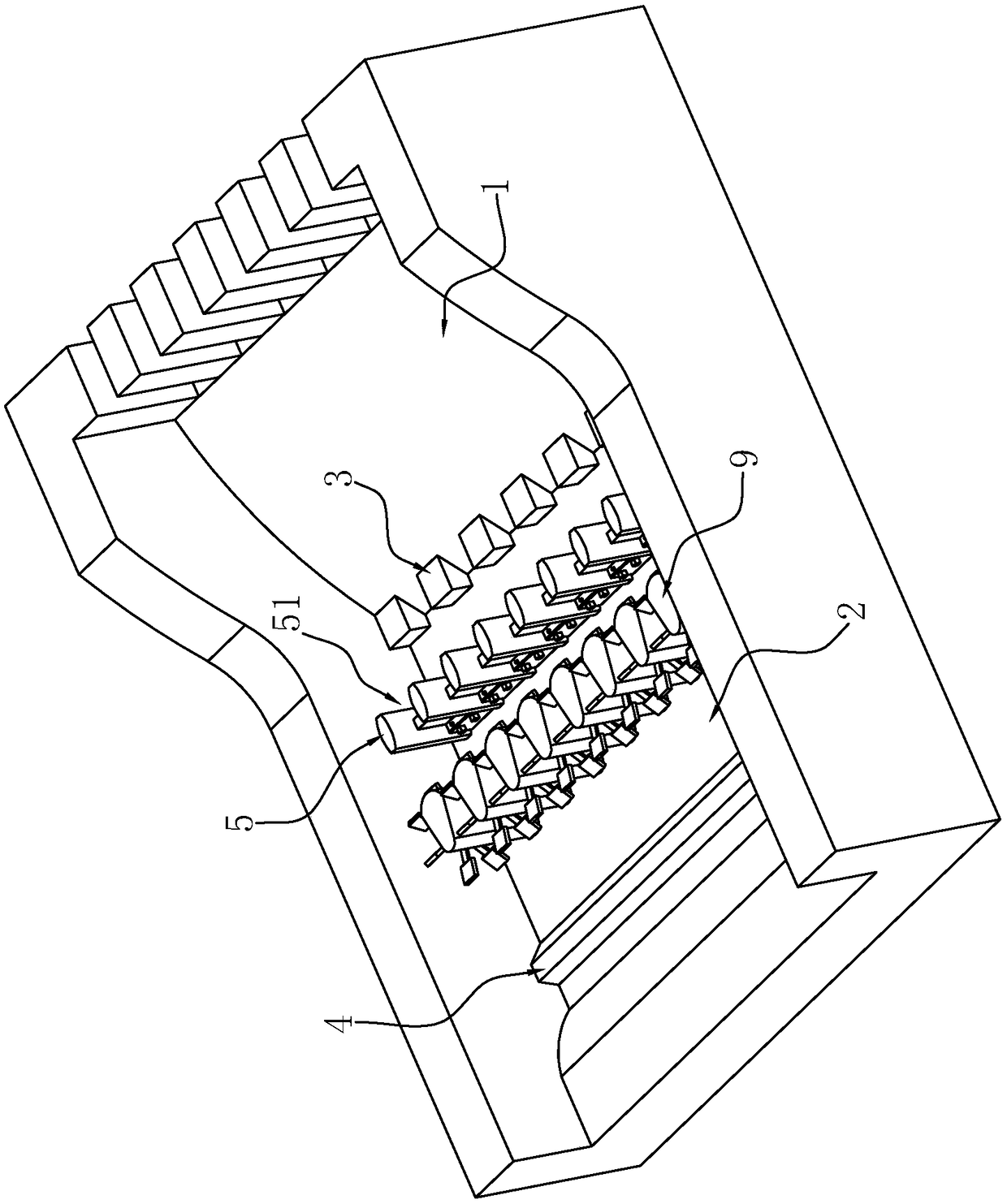
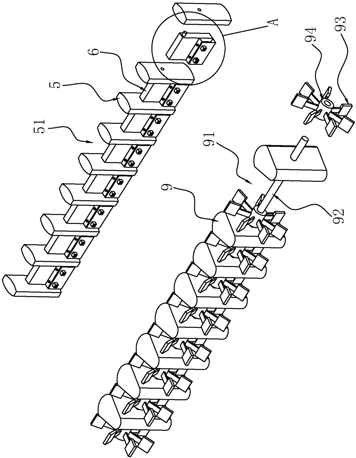
[0039] A new type of hydraulic engineering energy dissipation structure, such as figure 1 with figure 2 As shown, it includes the drainage surface 1 and the stilling pool 2 arranged at the bottom of the drainage surface 1. The junction of the drainage surface 1 and the stilling pool 2 is fixedly connected with a toe pier 3, and the tail end of the stilling pool 2 is fixedly connected with a tail sill 4. , the water-facing surface of the tail sill 4 is an inclined p...


PUM


Abstract

The invention discloses a novel hydraulic engineering energy dissipater structure, and relates to the field of hydraulic engineering energy dissipation. The structure comprises a drainage face and a stilling pool arranged at the bottom end of the drainage face, a plurality of toe piers are arranged at the joint between the drainage face and the stilling pool, and an end sill is fixedly connected to the tail end of the stilling pool. A plurality of baffle piers are fixedly connected with the interior of the stilling pool, a water through groove where water can pass is reserved between every twoadjacent baffle piers, and baffle blocks are arranged in the water through grooves, located between the adjacent baffle piers and rotationally connected with the baffle piers. The rotary connection positions between the baffle blocks and the baffle piers are located at the positions close to the top ends of the baffle blocks. Water flows into the stilling pool, the baffle piers in the stilling pool block water, and therefore secondary consumption is carried out on water. The baffle blocks are rotationally connected with the baffle piers, water jacks open the baffle blocks and flows into the end sill through the water through grooves, water energy consumption can be increased since water jacks open the baffle blocks, and therefore water impact energy is reduced.

Description

technical field [0001] The invention relates to the field of water conservancy engineering energy dissipators, and more specifically relates to a novel water conservancy engineering energy dissipater structure. Background technique [0002] The energy dissipator is an engineering facility built to eliminate the excess kinetic energy of the rapid discharge of the discharge structure or the drop structure, and to prevent or reduce the erosion and damage of the water flow to the hydraulic structure and its downstream canals. [0003] The existing technology can refer to the Chinese invention patent with the authorized announcement number CN103266584B, which discloses a water conservancy project energy dissipation structure, including a sill arranged behind the gate pier, the rear end of the sill connects to the stilling pool, and the stilling pool An effective ridge is set at the end; the facing surface of the ridge is a slope surface, and the top of the facing surface is folde...

Claims


Application Information

Patent Timeline
IPC IPC(8): E02B8/06
CPCE02B8/06
Inventor 冯启城
Owner 四川启创建设工程有限公司
Why Eureka
Try Eureka