Activating jig for screen of electronic device

A technology for electronic devices and screens, applied in identification devices, workpiece clamping devices, manufacturing tools, etc., can solve the problems of dirt, release paper easily blown up, etc.

Active Publication Date: 2018-12-21
OPPO CHONGQING INTELLIGENT TECH CO LTD
View PDF7 Cites 0 Cited by
  • Summary
  • Abstract
  • Description
  • Claims
  • Application Information

AI Technical Summary

Problems solved by technology

[0002] In the related art, when the lower mold of the activation fixture is used to activate the front hole of the screen, since the adhesive surface of the release paper bonded to the front hole is small, the release paper is easy to be blown up, resulting in the front hole of the screen. White spots, hairs, dirt, etc. appear on the hole

Method used


Image

  • Activating jig for screen of electronic device
  • Activating jig for screen of electronic device
  • Activating jig for screen of electronic device

Examples


Embodiment Construction

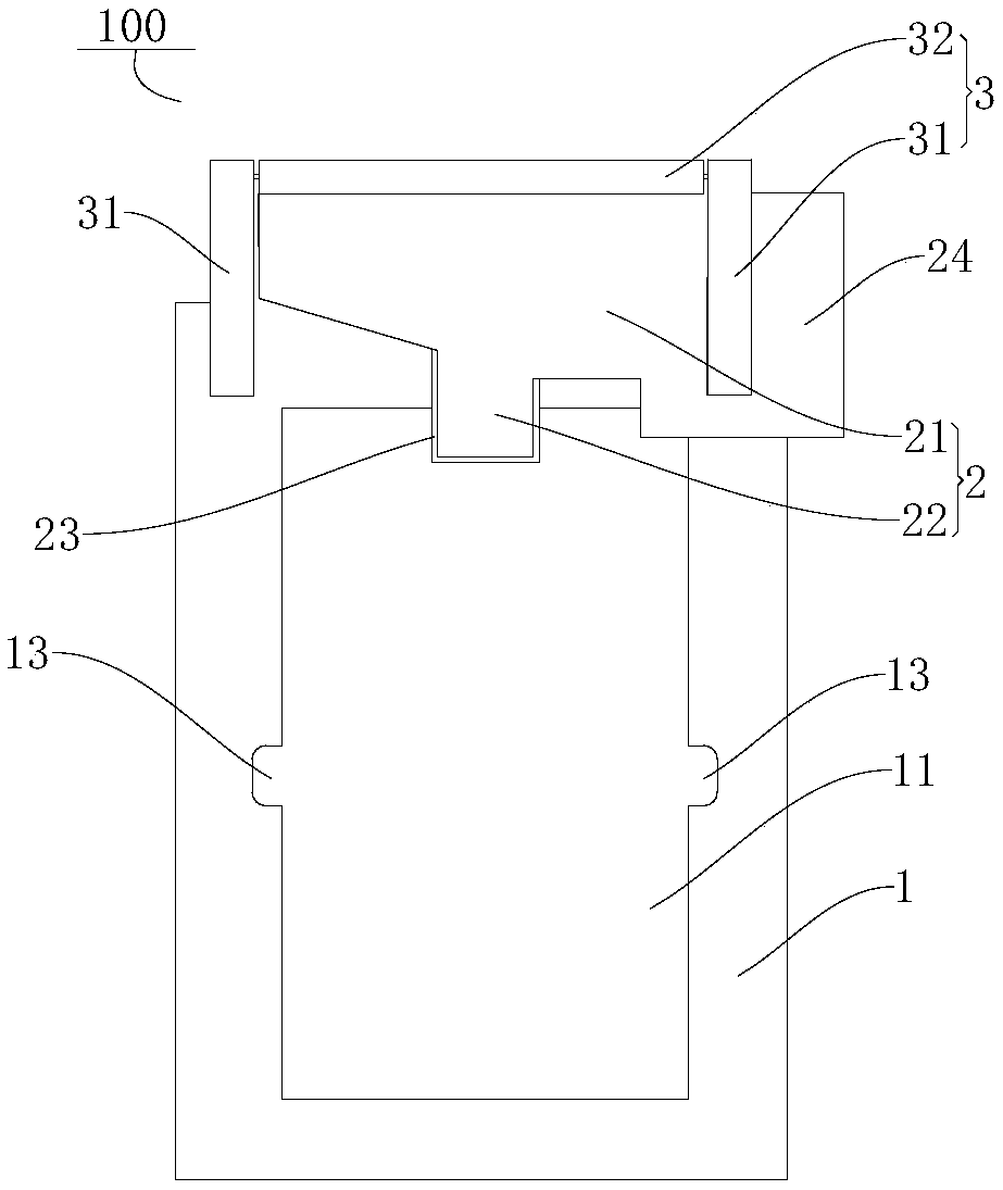
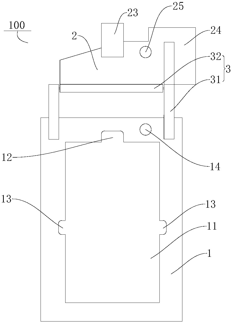
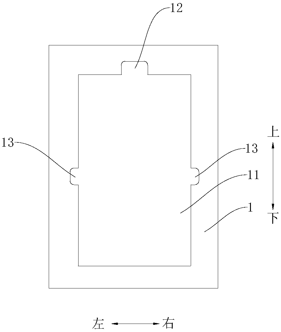
[0016] Embodiments of the present application are described in detail below, examples of which are shown in the drawings, wherein the same or similar reference numerals denote the same or similar elements or elements having the same or similar functions throughout. The embodiments described below by referring to the figures are exemplary, and are only for explaining the present application, and should not be construed as limiting the present application.

[0017] In the description of the present application, it should be understood that the terms "length", "upper", "lower", "left", "right", "inner", "outer", "circumferential" and the like indicate an orientation or The positional relationship is based on the orientation or positional relationship shown in the drawings, which is only for the convenience of describing the application and simplifying the description, and does not indicate or imply that the referred device or element must have a specific orientation, be constructe...


PUM


Abstract

The invention discloses an activating jig for a screen of an electronic device. An open hole is formed in the screen of the electronic device, and release paper is arranged on the inner surface of thescreen, and covers the open hole; the activating jig comprises a lower mold and a cover plate, wherein a containing groove for containing the screen is formed in the lower mold; the cover plate is movably arranged on the lower mold, the cover plate can move between a first position shielding a part of the containing groove and a second position exposing out of the containing groove, and when thecover plate is located at the first position, the cover plate covers the release paper. According to the activating jig, the cover plate is arranged on the lower mold, and can move between the first position shielding a part of the containing groove and the second position exposing out of the containing groove, when the cover plate is located at the first position, the cover plate covers the release paper, and when the activating jig is used for activating, the cover plate is located at the first position, and the cover plate covers the release paper on the screen; it is avoided that the release paper is blown during activating, and white points, broken filaments, squalidity and the like appear at the open hole of the screen.

Description

technical field [0001] The present application relates to the technical field of processing and manufacturing of electronic devices, in particular to an activation jig for screens of electronic devices. Background technique [0002] In the related art, when the lower mold of the activation fixture is used to activate the front hole of the screen, since the adhesive surface of the release paper bonded to the front hole is small, the release paper is easy to be blown up, resulting in the front hole of the screen. White spots, hairs, dirt, etc. appear at the hole. Contents of the invention [0003] This application aims to solve at least one of the technical problems existing in the prior art. For this reason, the present application proposes an activation jig for a screen of an electronic device. The activation jig can prevent white spots, hairs, and dirt from appearing in openings of the screen. [0004] According to the activation jig for the screen of an electronic devi...

Claims


Application Information

Patent Timeline
Patent Type & Authority Applications(China)
IPC IPC(8): G09F9/00B25B11/00
CPCB25B11/00G09F9/00
Inventor 王利新
Owner OPPO CHONGQING INTELLIGENT TECH CO LTD
Why Eureka
Try Eureka