Heat-driven micro-pump experimental device and method based on micro-fluidic technology

A microfluidic technology and experimental device technology, which is applied in the field of micro-electromechanical systems, can solve the problems of low flow efficiency, large flow pulsation, and low driving voltage, and achieve the effects of improving flow efficiency, overcoming pulsation phenomena, and improving conversion efficiency

Active Publication Date: 2019-01-04
JIANGSU UNIV
View PDF6 Cites 3 Cited by
  • Summary
  • Abstract
  • Description
  • Claims
  • Application Information

AI Technical Summary

Problems solved by technology

[0004] The purpose of the present invention is to propose a low driving voltage, high flow efficiency, and can effectively overcome the pulsation phenomenon based on microfluidic technology, aiming at the defects of low flow efficiency, large flow pulsation and complex structure existing in thermally driven micropumps. Heat-driven micropump experimental device and experimental method of the experimental device

Method used


Image

  • Heat-driven micro-pump experimental device and method based on micro-fluidic technology
  • Heat-driven micro-pump experimental device and method based on micro-fluidic technology
  • Heat-driven micro-pump experimental device and method based on micro-fluidic technology

Examples


Embodiment Construction

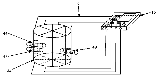
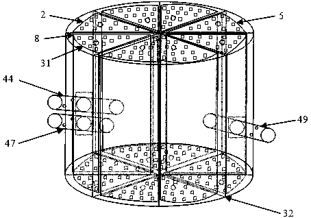
[0045] see figure 1 , a heat-driven micropump experimental device based on microfluidic technology described in the present invention is composed of two modules: a heat-driven micropump 32 and a microcontroller module 16 . Both the heat-driven micropump 32 and the microcontroller module 16 are independent modules that can be freely placed on a horizontal plane, and the two modules are connected by multiple wires 6 . There are two liquid inlet pipes and a liquid outlet pipe 49 on the side wall of the heat-driven micropump 32, and the two liquid inlet pipes are respectively the first liquid inlet pipe 44 and the second liquid inlet pipe 47 with the same structure, and the first liquid inlet pipe The pipe 44 and the second liquid inlet pipe 47 are arranged up and down, and are used to add two different kinds of liquids to the interior of the heat-driven micropump 32 respectively. The liquid outlet pipe 49 is on the opposite side of the two liquid inlet pipes, and is used for the...


PUM


Abstract

The invention discloses a heat-driven micro-pump experimental device and method for pumping micro-fluid based on micro-fluidic technology in the field of microelectronic mechanical systems. The heat-driven micro-pump is driven by a liquid flowing-in micro-valve, six liquid flowing micro-valves and a liquid flowing-out micro-valve; a liquid inlet pipe, a liquid flow area and a liquid outlet pipe are combined into a whole, temperature sensors are arranged near heating resistors, and are used for detecting the temperature of different positions inside the heat-driven micro-pump in real time and feeding back to a microcontroller, the gas expansion force generated by heating and the deformation between materials are used as driving force, and the liquid is conveyed in the circulating heating mode for each part, so that the conversion between the heat energy and the mechanical energy is realized, the large driving force can be provided, the large diaphragm deformation is obtained under the low driving voltage, the conversion efficiency between the heat energy and the mechanical energy is improved, the stable flow can be provided, and the pulsation phenomenon of the micro-pump is effectively overcome.

Description

technical field [0001] The invention belongs to the field of microelectromechanical systems, relates to a heat-driven micropump experimental device and method based on microfluidic technology, and is a delivery device for pumping microfluid. Background technique [0002] Micro-motors, also known as micro-pumps, are the power source for micro-fluid transport. As an important micro-executive component, micro-pumps can be widely used in drug delivery, blood transport, DNA synthesis, micro-total analysis systems, and micro-fuel cells. . Micropumps can be mainly divided into piezoelectric-driven micropumps, electrostatically driven micropumps, electro-hydraulic power micropumps, and electroosmotic-driven micropumps. The above-mentioned driving methods each have different advantages, but also have their own shortcomings. For example, the driving voltage of the piezoelectric-driven micropump is high; the driving force of the electrostatic-driven micropump is small, and the deform...

Claims


Application Information

Patent Timeline
Patent Type & Authority Applications(China)
IPC IPC(8): F04B9/12F04B43/06F04B49/06F04B51/00F04B53/10F03G7/06
Inventor 潘辰杨宁周晓迪张猛
Owner JIANGSU UNIV
Why Eureka
Try Eureka