Quadruped robot and leg joint structure

A quadruped robot and joint structure technology, applied in the field of robotics, can solve the problems of limited hydraulic cylinder stroke, difficulty in passing tasks for high-load quadruped robots, and insufficient joint flexibility, achieving reasonable stress, shortened dynamic response time, smooth motion effect

Active Publication Date: 2019-01-11
SINOPEC OILFIELD EQUIP CORP +1
View PDF11 Cites 14 Cited by
  • Summary
  • Abstract
  • Description
  • Claims
  • Application Information

AI Technical Summary

Problems solved by technology

For high-load quadruped robots, hydraulic cylinders are usually used to drive them, but due to the limited stroke of hydraulic cylinders, their joint flexibility is far less than that of motor-driven joints.
For some environments that require significant contraction or expansion of joints, it is difficult for a high-load quadruped robot driven by a hydraulic cylinder to complete the task of passing through it.

Method used


Image

  • Quadruped robot and leg joint structure
  • Quadruped robot and leg joint structure
  • Quadruped robot and leg joint structure

Examples


Embodiment Construction

[0023] In order to better understand the present invention, the invention will be described in detail below in conjunction with the accompanying drawings and specific examples.

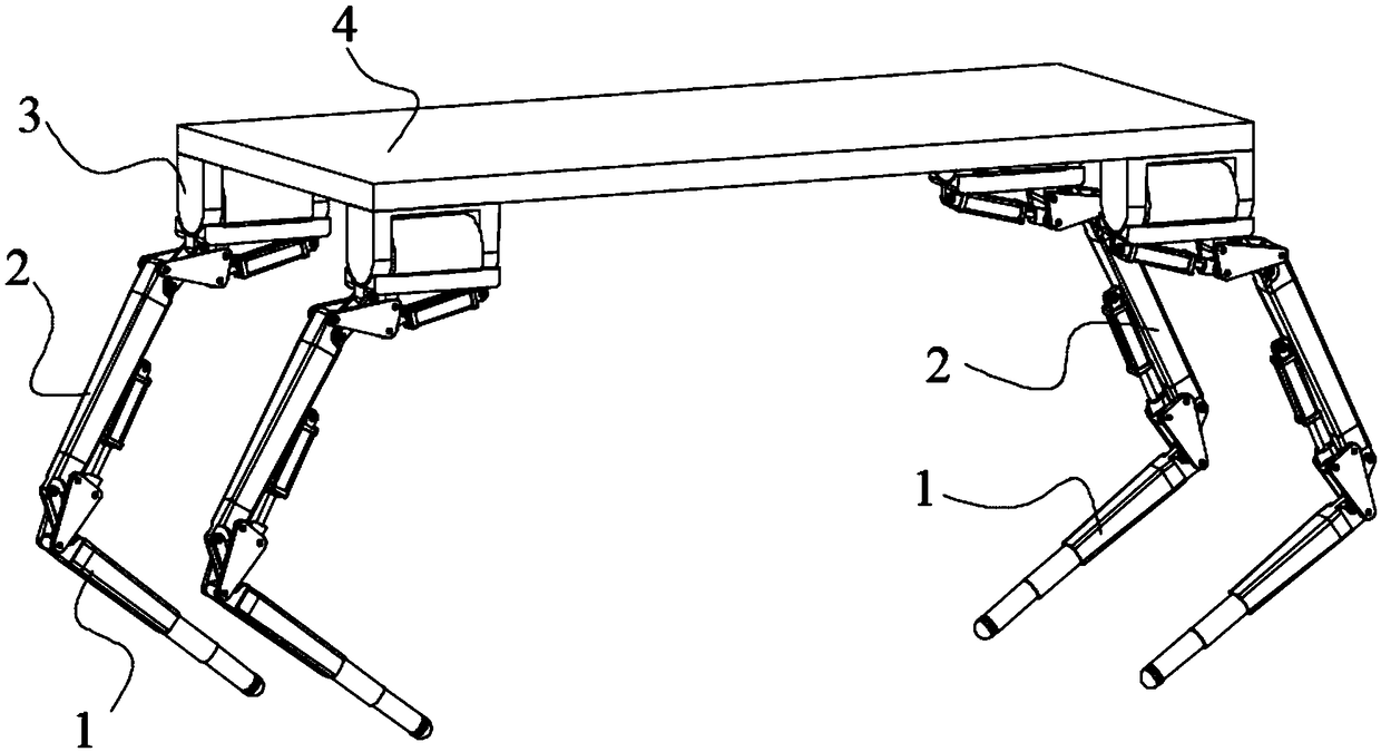
[0024] The whole quadruped robot is composed of calf 1, thigh 2, side swing 3 and robot platform 4. The side swing 3 is fixedly installed on the bottom of the four corners of the robot platform 4. The thigh 2 is installed on the side swing 3 through bending joints. The top of the calf 1 The leg joint structure is installed on the bottom of the thigh 2, and the bottom of the lower leg 1 walks on the ground. The gaits of walk, trot, pace, bound, and rotary gallop can be performed, and obstacles of a certain height or width can be crossed or stepped over.

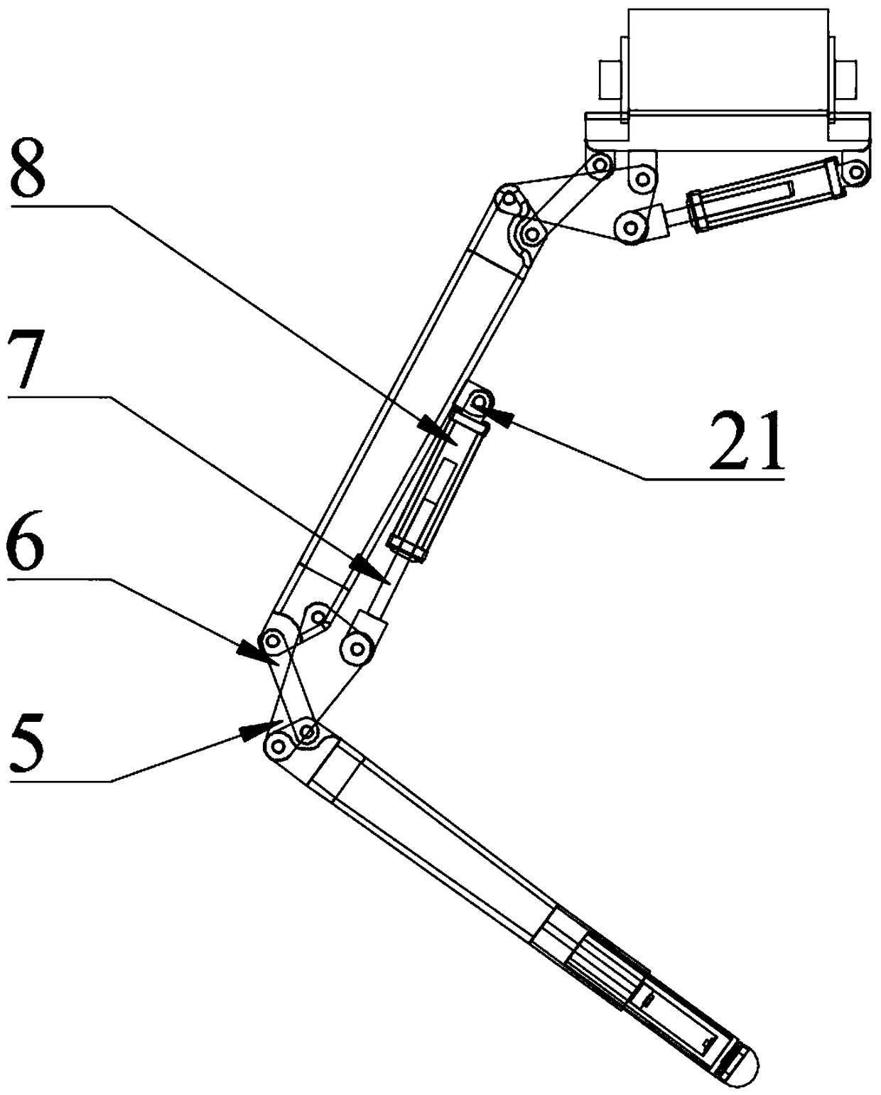
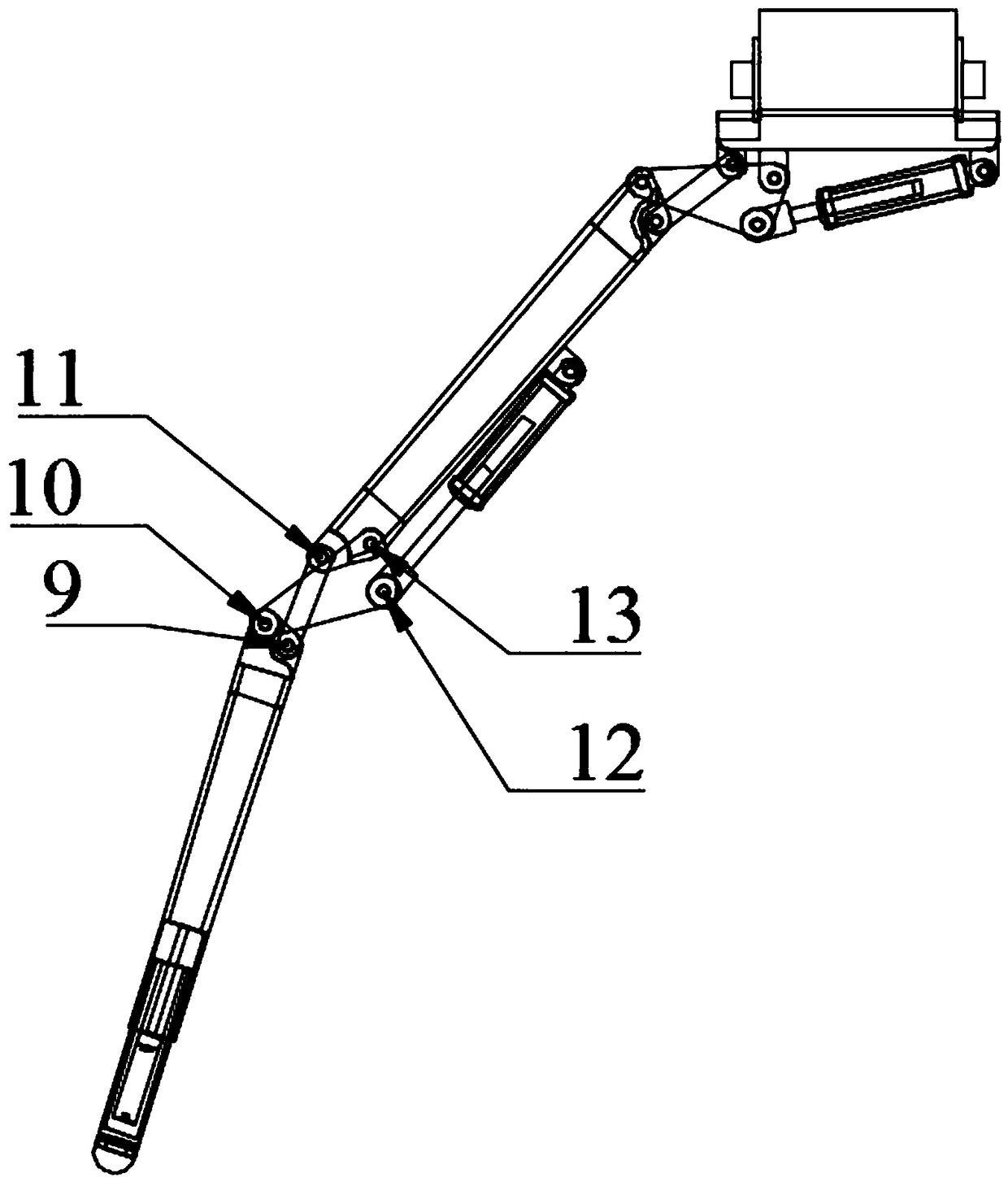
[0025] The leg joint structure includes a thigh 2 and a calf 1, and the thigh 2 and the calf 1 are connected through a large connecting rod 5, a small connecting rod 6 and a hydraulic cylinder 8, and one end of the large connecting rod 5 is connected ...


PUM


Abstract

The invention discloses a quadruped robot and a leg joint structure. The quadruped robot comprises a robot platform and four feet arranged below the robot platform, each foot includes a side swing connected in turn, thigh and calf, a lateral pendulum is fixedly mount on the robot platform; the thigh and the calf are connected to the hydraulic cylinder through the large connecting rod and the smallconnecting rod; the large connecting rod is connected to the thigh and the calf through a first hinge and a second hinge, The small connecting rod is respectively connected with the upper leg and thelower leg through a fourth hinge and a fifth hinge, the upper connecting rod and the small connecting rod are arranged crosswise, the upper connecting rod is further provided with a third hinge, thethird hinge is located on the inner side of the bent upper leg and the lower leg, one end of the hydraulic cylinder is connected with the third hinge, and the other end is installed in the middle of the thigh through a sixth hinge. As the leg joint structure of the invention makes the leg joint have a smaller turn radius, the complete walking bending action of the joint can be complete by adoptinga smaller hydraulic cylinder stroke.

Description

technical field [0001] The invention belongs to the field of robots, and relates to a multi-legged robot, in particular to a quadruped robot and a leg joint structure. Background technique [0002] In the field of quadruped robots, due to the different requirements for their work tasks, the structural design and driving design of quadruped robots are also different. For quadruped robots with relatively small loads, quadruped robots that require high motion performance usually use motors to drive their joints to rotate. The advantage is that the joints have a relatively large range of motion, stronger passing performance, and can adapt to more complex environments. For high-load quadruped robots, hydraulic cylinders are usually used to drive them, but due to the limited stroke of hydraulic cylinders, the flexibility of their joints is far less than that of motor-driven joints. For some environments that require significant contraction or expansion of joints, it is difficult ...

Claims


Application Information

Patent Timeline
Patent Type & Authority Applications(China)
IPC IPC(8): B62D57/032
CPCB62D57/032
Inventor 蔡志宏赵慧黄家文徐军彭太峰
Owner SINOPEC OILFIELD EQUIP CORP
Why Eureka
Try Eureka