Sliding cam system

A sliding cam, cam technology, applied in the direction of engine components, engine control, machine/engine, etc.

Active Publication Date: 2019-02-01
MAN NUTZFAHRZEUGE AG
View PDF11 Cites 0 Cited by
  • Summary
  • Abstract
  • Description
  • Claims
  • Application Information

AI Technical Summary

Problems solved by technology

The arrangement of the drive for deflecting the cam carrier ...

Method used


Image

  • Sliding cam system
  • Sliding cam system
  • Sliding cam system

Examples


Embodiment Construction

[0039] The embodiments shown in the figures are at least partially identical, such that similar or identical parts bear the same reference signs, and in order to avoid repetition they are also explained with reference to other embodiments or to the description of the figures.

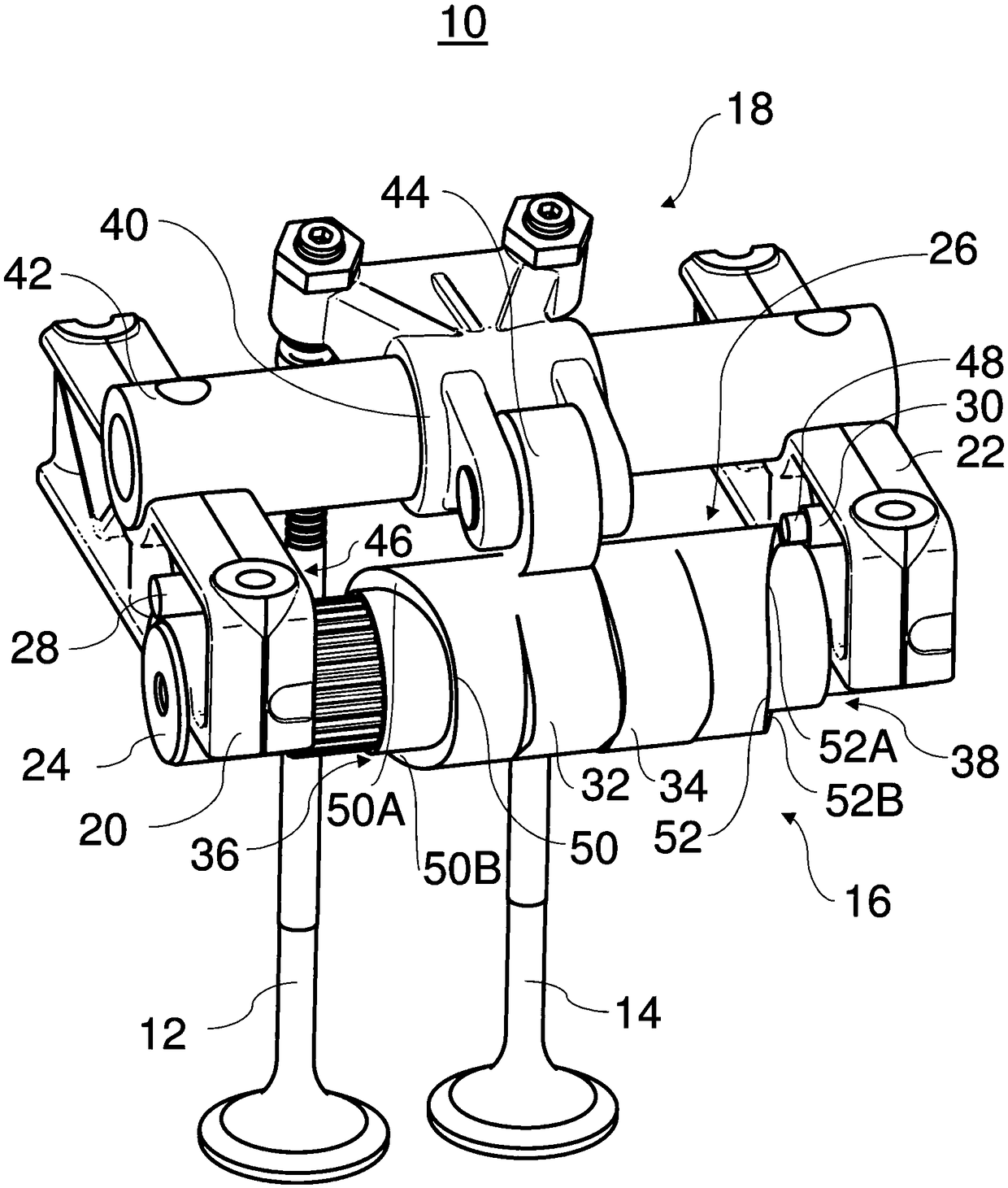
[0040] figure 1 A variable valve mechanism 10 is shown. For example, the variable valve train 10 may be part of an internal combustion engine of a commercial vehicle, in particular a truck or a bus. The variable valve mechanism 10 includes a first gas exchange valve 12, a second gas exchange valve 14, a sliding cam system 16, a force transfer device 18, a first bearing housing (bearing body) 20 and a second bearing housing (bearing body) 22.

[0041] The variable valve mechanism 10 is used to regulate the control of the ventilation valves 12 , 14 . In particular, the opening time, closing time and / or valve lift of the gas exchange valves 12, 14 can be adjusted. The gas exchange valves 12, 14 can be i...


PUM


Abstract

The invention relates to a sliding cam system 16 for an internal combustion engine. The sliding cam system 16 includes a cam shaft 24 and a cam carrier 26, arranged rotationally fixedly and axially movably on the cam shaft 24. The cam carrier 26 includes a first shifting gate 36 and a second shifting gate 38. The sliding cam system 16 includes a first actuator 28 with an element 46 able to move along a longitudinal axis of the cam shaft 24, especially a pin, which can be brought into contact with the first shifting gate 36 for the axial movement of the cam carrier 26 in a first direction. Thesliding cam system 16 includes a second actuator 30 with an element able to move along the longitudinal axis of the cam shaft 24, especially a pin, which can be brought into contact with the second shifting gate 38 for the axial movement of the cam carrier 26 in a second direction which is opposite to the first direction.

Description

technical field [0001] The invention relates to a sliding cam system for an internal combustion engine. Background technique [0002] Valve-controlled internal combustion engines have one or more controllable intake or exhaust valves for each cylinder. Variable valve trains provide the flexibility to control valves to vary opening time, closing time and / or valve lift (Ventilhubs). In this way, engine operation can be adapted to specific load conditions, for example. For example, variable valve trains can be realized by so-called sliding cam systems. [0003] DE 19611641 C1 discloses an example of such a sliding cam system by which the gas exchange valve can be driven with a plurality of different lift curves. For this purpose, a sliding cam with at least one cam portion comprising a plurality of cam tracks is non-rotatably and axially displaceable mounted on the camshaft; an actuator in the form of a pin is introduced radially into the sliding cam from the outside. In th...

Claims


Application Information

Patent Timeline
IPC IPC(8): F01L13/00F01L1/047
CPCF01L1/047F01L13/0036F01L2001/0473F01L2013/0078F01L1/181F01L1/26F01L2013/0052F01L2013/101F01L2305/00F02D13/02F01L1/267F01L2013/103F01L2013/105F01L2013/106
Inventor 斯特凡·希施曼延斯·迪特里希
Owner MAN NUTZFAHRZEUGE AG
Why Eureka
Try Eureka