Thrust load applying mechanism, and disk device having thrust load applying mechanism

A pressure mechanism and thrust load technology, which is applied in data recording, instrumentation, information storage, etc., can solve the problems that hinder the smooth operation of the optical pickup moving mechanism, achieve smooth operation, reduce the influence of motor cogging, and improve accuracy Effect

Inactive Publication Date: 2003-12-03
MITSUMI ELECTRIC CO LTD
View PDF0 Cites 0 Cited by
  • Summary
  • Abstract
  • Description
  • Claims
  • Application Information

AI Technical Summary

Problems solved by technology

They become the cause of hindering the smooth o

Method used


Image

  • Thrust load applying mechanism, and disk device having thrust load applying mechanism
  • Thrust load applying mechanism, and disk device having thrust load applying mechanism
  • Thrust load applying mechanism, and disk device having thrust load applying mechanism

Examples


Embodiment Construction

[0073] Preferred embodiments of the disk device of the present invention will be described below with reference to the accompanying drawings.

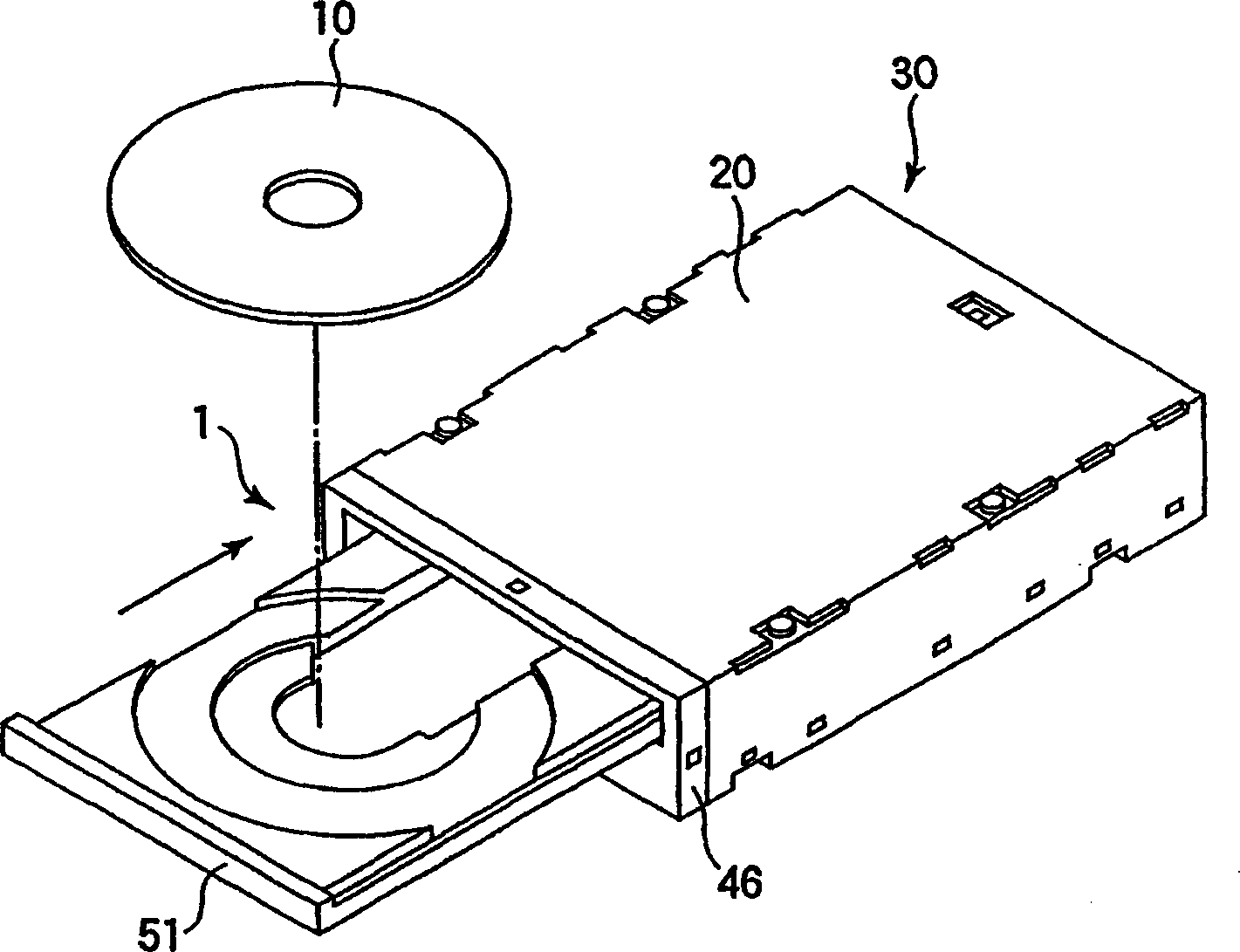
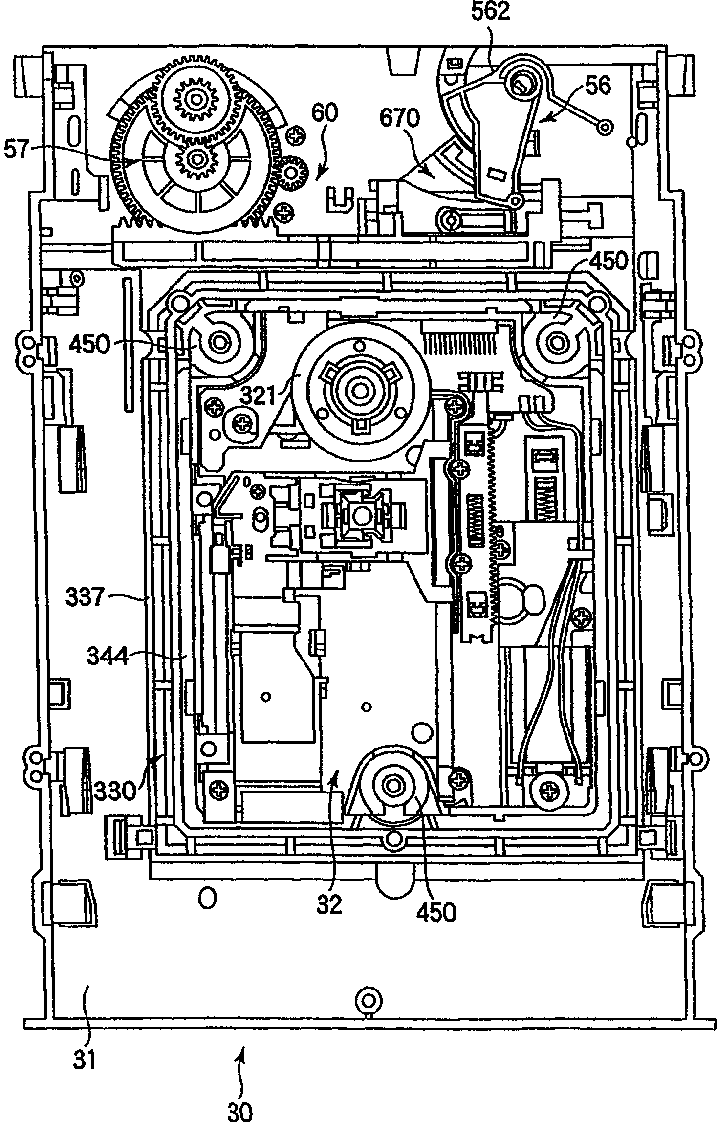
[0074] figure 1 is a perspective view showing the overall structure of the disk device of the present invention, figure 2 is a plan view of the main body of the disk drive.

[0075] Such as figure 1 As shown, the disc device 1 is an optical disc device for reproducing, recording, and reproducing discs 10 such as CDs and DVDs, and consists of a device main body 30 housed in a case 20 (refer to figure 2 ) and a disc tray 51 for transporting the disc 10 that moves in the front-rear direction (horizontal direction) relative to the apparatus main body 30.

[0076] Such as figure 2 As shown, the device main body 30 has a printed circuit board (not shown) and a frame 31 provided on the printed circuit board. As described above, the device main body 30 is accommodated in the case 20 formed of a thin metal plate.

[0077] The printed c...


PUM


Abstract

A thrust load applying mechanism, and a disk device having the thrust load applying mechanism. In an optical pickup moving mechanism (35) for moving an optical pickup (351) by a worm (361) formed with thread-like teeth, a thrust load applying mechanism (38) disposed at the front end of the worm (361) and adapted to abut against the front end of the worm (361) to urge the worm (361) from the front end toward the base end, thereby controlling the axial movement of the worm (361), is composed of a pressing member (381) abutting against the worm (361), a compression coil spring (400) for pressing the pressing member (381) from the front end to the base end of the worm (361), and a support member (410) supporting the pressing member (381) and compression coil spring (400), wherein the worm (361) and compression coil spring (400) are arranged so that a rotatable shaft (362) including the worm (361) is substantially axially aligned with the compression coil spring (400).

Description

technical field [0001] The present invention relates to a thrust load pressurizing mechanism for preventing movement of a rotary shaft of a helical motor of an optical pickup moving mechanism for a disk drive device. Background technique [0002] For example, in disk devices such as CD-ROM drive, CD-R / RW drive, DVD-ROM drive, and DVD-RW drive, an optical pickup moving mechanism is used to move an optical pickup or the like in the radial direction of the disk. [0003] The optical pick-up moving structure generally includes: a slide block (stand) freely slidably guided on the guide rod, a rack mounted on the slide block, a reduction gear meshed with the rack drive, and a forward and reverse A rotating DC motor, the gear of which the DC motor meshes with the reduction gear is installed on the rotating shaft. In order to reduce noise while reducing the size of the reduction mechanism, the DC motor generally uses a motor (hereinafter referred to as a helical motor) in which a w...

Claims


Application Information

Patent Timeline
IPC IPC(8): G11B7/085G11B21/02
CPCG11B21/02G11B7/08582
Inventor 中村光典荒井丰和真部悟
Owner MITSUMI ELECTRIC CO LTD
Why Eureka
Try Eureka