
Battery

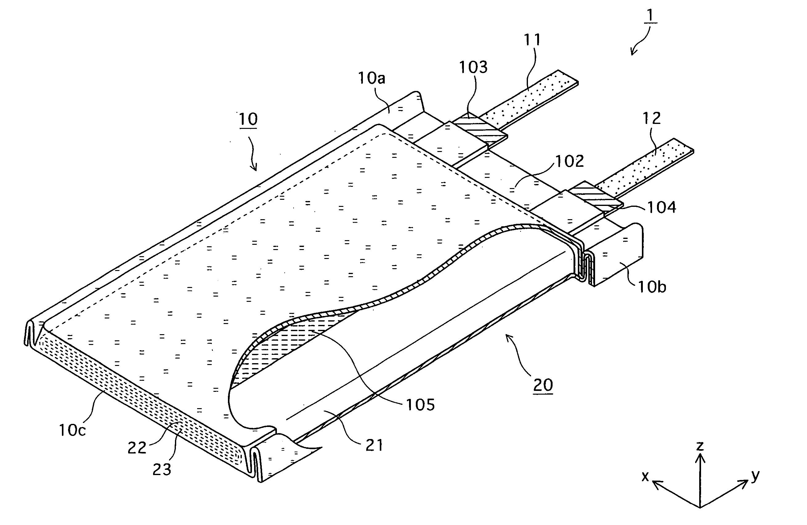
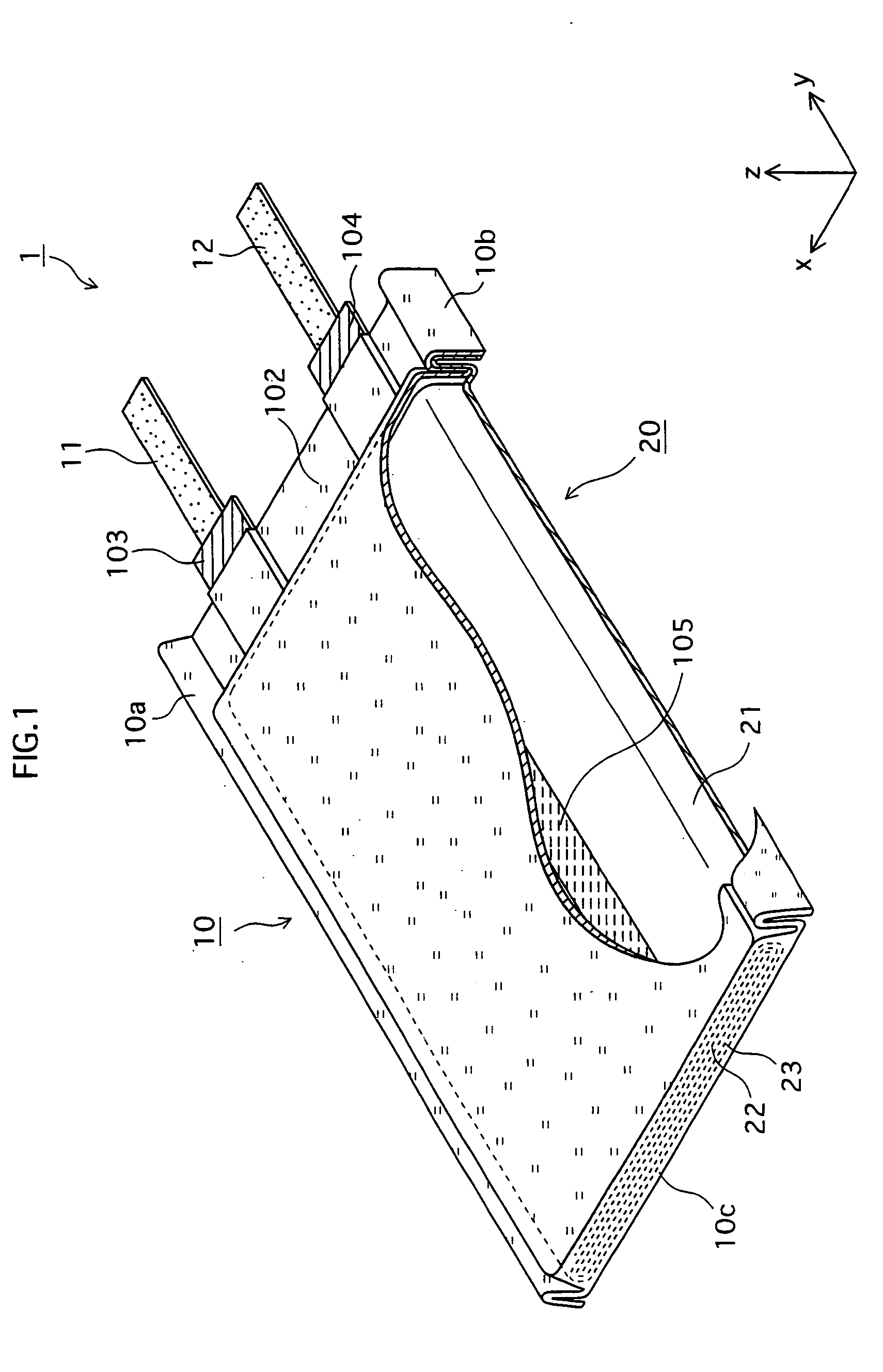
a battery and internal structure technology, applied in the field of internal structure of batteries, can solve the problems of deterioration, shrinkage, softening or shrinkage of tape, and affecting the performance of batteries, so as to prevent unnecessary shrinkage of tape, improve heat resistance, and shrink hardly.

Inactive Publication Date: 2006-03-02
SANYO ELECTRIC CO LTD
View PDF5 Cites 49 Cited by
  • Summary
  • Abstract
  • Description
  • Claims
  • Application Information

AI Technical Summary

Benefits of technology

[0013] The present invention, having been conceived in light of the aforementioned problem, has an object of providing a battery such as a laminated battery, which is prevented from deterioration of tape used inside the battery, and so has favorable battery performances.
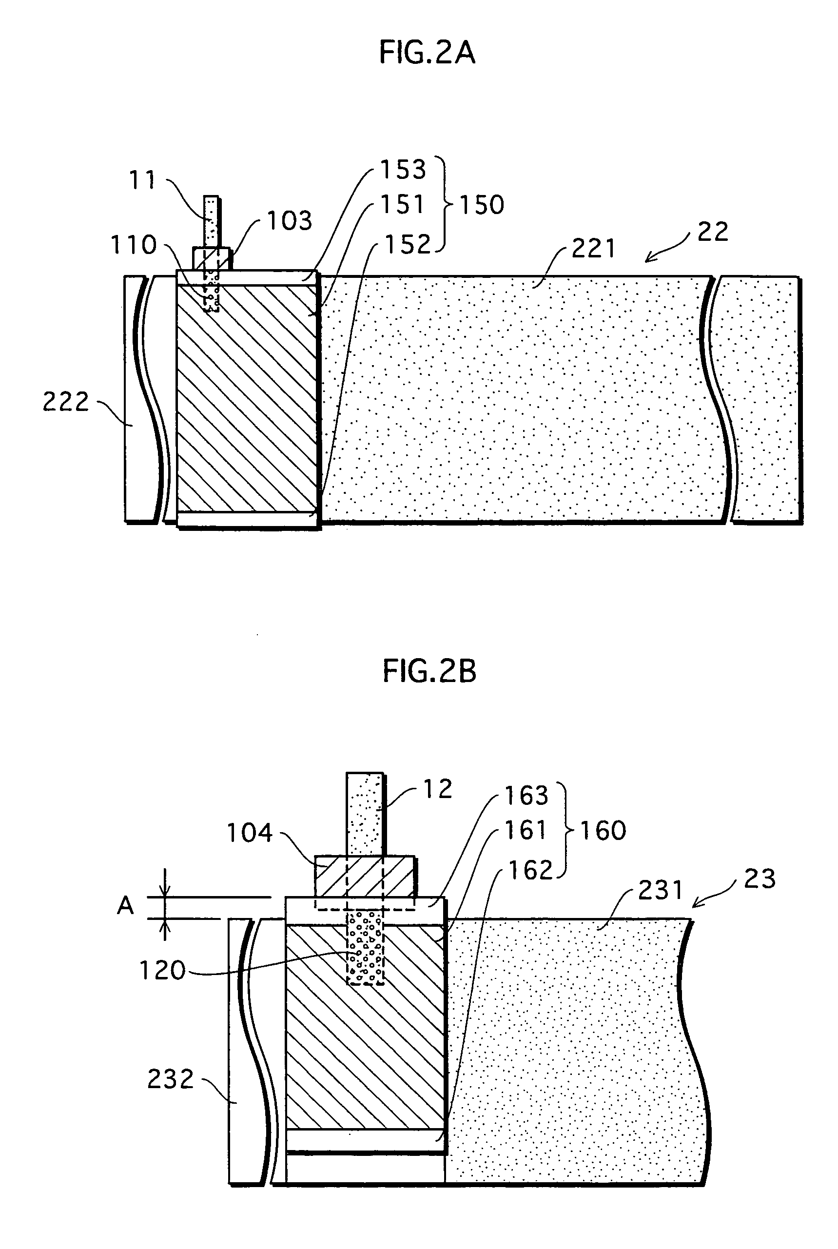
[0015] According to the above-stated battery construction, a cast polyolefin excellent in heat resistance is used inside the casing. Therefore the battery according to the present invention has improved battery performance compared to a conventional structure that uses orientated polyolefin.
[0017] Therefore, if such a cast polyolefin is used as a material of tape inside the battery, the tape would not shrink due to heat. This prevents exposure of the power generating element and the connection part between the tabs and the corresponding electrode plates, which are covered with the tape. This helps effectively prevent occurrence of short, and so helps offer stable battery performances.
[0018] When the present invention is applied to a laminated battery, it also produces an advantageous effect against heat influence in the heating processing (laminate processing) by which the laminate casing is sealed, in addition to the above-stated effect. For example, the vicinity of the tabs near the sealing parts tends to be exposed to high heat in the heating processing. However, by making the vicinity of the tabs by cast polyolefin as in the present invention, the sealing is performed favorably.

Problems solved by technology

However, the tape made of orientated polyolefin has relatively low heat resistance, and so can have a detrimental effect on the battery performance.
In the thermo-compression bonding, however, such tape can deteriorate (e.g. softens or shrinks).
Such adverse effect of heat is also expected to happen when the battery undergoes overheating due to battery anomalies.
Such deterioration of tape is desired to be prevented because if the tape is used as the protection tape for a tab, it can cause the tab to be exposed to come into contact with a different electrode plate thereby causing short.
As stated above, the current laminated batteries have a problem to be solved.
This particular problem is common to any types of battery that uses therein the same kind of tape as stated above.

Method used


Image

  • Battery
  • Battery
  • Battery

Examples


embodiment example 1

[0060] As an active material for the positive electrode, a mixture, in which spinel-structure lithium manganese oxide (e.g. LiMn2O4), and lithium cobalt oxide (e.g. LiCoO2) are mixed in a certain ratio, is used.

[0061] Note that, although not used in the present embodiment example, either lithium manganese oxide or lithium cobalt oxide, which is mixed with a different type of chemical element, may also be used as the active material for the positive electrode.

[0062] To this mixture as a positive-electrode active material, a carbon conductive agent and graphite are mixed in a predetermined amount. Then the resulting mixture is mixed with a fluoropolymer-based bonding agent at a predetermined ratio, thereby obtaining a positive-electrode mixture. This positive-electrode mixture is applied onto both surfaces of the aluminum foil (i.e. a core of the positive electrode), and is dried. After being dried, the aluminum foil to which the positive-electrode mixture has been applied is rolled...


PUM

PropertyMeasurementUnit
lengthaaaaaaaaaa
thicknessaaaaaaaaaa
widthaaaaaaaaaa

Abstract

Provided is a battery such as a laminated battery, which has a favorable battery performance by being endowed with heat resistance. In the laminated battery 1, tab resins 103, 104, securing tape 105, protection tape 150, and protection tape 160 are made of cast polyolefin having heat resistance.

Description

BACKGROUND OF THE INVENTION [0001] (1) Field of the Invention [0002] The present invention relates to an internal structure of a battery. Particularly, the present invention relates to a technology for improving heat resistance of a laminated battery such as a lithium polymer battery. [0003] (2) Related Art [0004] Recent years have seen widespread use of small electronic devices such as portable telephones, pocket personal computers, portable audio devices, digital cameras, and personal digital assistances (PDA). In accordance with this trend, there is a rapidly increased demand for thin and light batteries that allow a large capacity. In particular, laminated batteries, each equipped with a lithium polymer electrolyte and a laminate casing, are already used for such small electronic devices, because of being flexible, extremely thin, light, and of allowing a large capacity at the same time. [0005] A power generating element of a conventional laminated battery is generated in the fo...

Claims


Application Information

Patent Timeline
Patent Type & Authority Applications(United States)
IPC IPC(8): H01M2/18H01M2/26H01M2/08H01M10/05H01M10/052H01M10/0565H01M10/058H01M10/0587H01M50/178H01M50/186H01M50/193H01M50/409H01M50/489H01M50/491H01M50/531H01M50/55H01M50/553
CPCH01M2/08H01M2/16H01M2/26H01M2/30H01M2/348Y02E60/122H01M4/621H01M4/622H01M10/052H01M10/0565H01M10/0587H01M4/13Y02E60/10H01M50/409H01M50/581H01M50/531Y02P70/50H01M50/491H01M50/186H01M50/489H01M50/193H01M50/55H01M50/178H01M50/553H01M50/20H01M50/10H01M10/04
Inventor KODAMA, YASUNOBU
Owner SANYO ELECTRIC CO LTD
Learn More