Split lock screw fastener assembly and method

a screw and screw technology, applied in the direction of screws, fastening means, fastener tools, etc., can solve the problems of inapplicability, inapplicability, and inability to meet the needs of users, and achieve the effect of avoiding thread galling

Inactive Publication Date: 2005-06-21
BRESLIN MARY A
View PDF16 Cites 46 Cited by
  • Summary
  • Abstract
  • Description
  • Claims
  • Application Information

AI Technical Summary

Benefits of technology

[0009]It is an object of the invention to provide a locking split bolt and screw set pin assembly that avoids galling of threads of the screw set pin into threads of a bore extending through the split bolt without strain and injury to the threads of either the bolt or screw set pin.
[0010]It is another object of the invention to provide a locking split bolt and screw set pin assembly that provides minimum frictional resistance to tightening of the screw set pin into a bore extending through the split bolt.
[0011]It is another object of the invention to provide a locking split bolt and screw set pin assembly that provides maximum mechanical advantage for tightening of the screw set pin into a bore extending through the split bolt to expand a threaded split distal portion of the bolt against threads of a receiving hole into which the bolt has been tightened and to lock the threads of the split bolt into place in the receiving hole.
[0012]It is another object of the invention to provide a locking split bolt and screw set pin assembly that provides maximum mechanical advantage for tightening of the screw set pin into a bore extending through the split bolt to expand a threaded split distal end portion of the bolt against threads of a receiving hole into which the bolt has been tightened to lock the bolt and screw set pin into place in the receiving hole and that also prevents loosening of the bolt and screw set pin due to various conditions, such as mechanical vibration and / or thermal cycling of a body in which the receiving hole is formed.
[0015]It is another object of the invention to provide a locking fastener including a hollow split bolt and a screw set pin which can be reusable.
[0016]It is another object of invention to provide a true locking fastener that is easy to install without use of complicating components or accessories.

Problems solved by technology

Such galling would necessitate that an extremely large amount of torque be applied to the pin setscrew to advance it into the reduced-diameter portion of the bolt bore.
Also, there would be inadequate mechanical advantage of torque applied between the bolt end of the pin setscrew to advance the pin setscrew so as to develop sufficient outward force on the split distal end sections of the bolt to expand them and adequately lock the bolt into the bolt-receiving hole.
It would not be practical for the user to apply enough force to the pin setscrew to spread the distal split end of the bolt enough to cause an adequate locking effect, and the force would not be equally applied to all fingers to spread the bolt because of the diminishing root depth of the lead in threads of the bolt bore screw section as the pin setscrew is turned.
Furthermore, the prior art does not provide any way of locking the pin setscrew to the bolt into when it is screwed into the bolt.
Despite the efforts in the prior art, there has been a very long and unfulfilled need for a practical, highly reliable self-locking bolt.
No really reliable solution to this problem has ever been provided.

Method used


Image

  • Split lock screw fastener assembly and method
  • Split lock screw fastener assembly and method
  • Split lock screw fastener assembly and method

Examples


Embodiment Construction

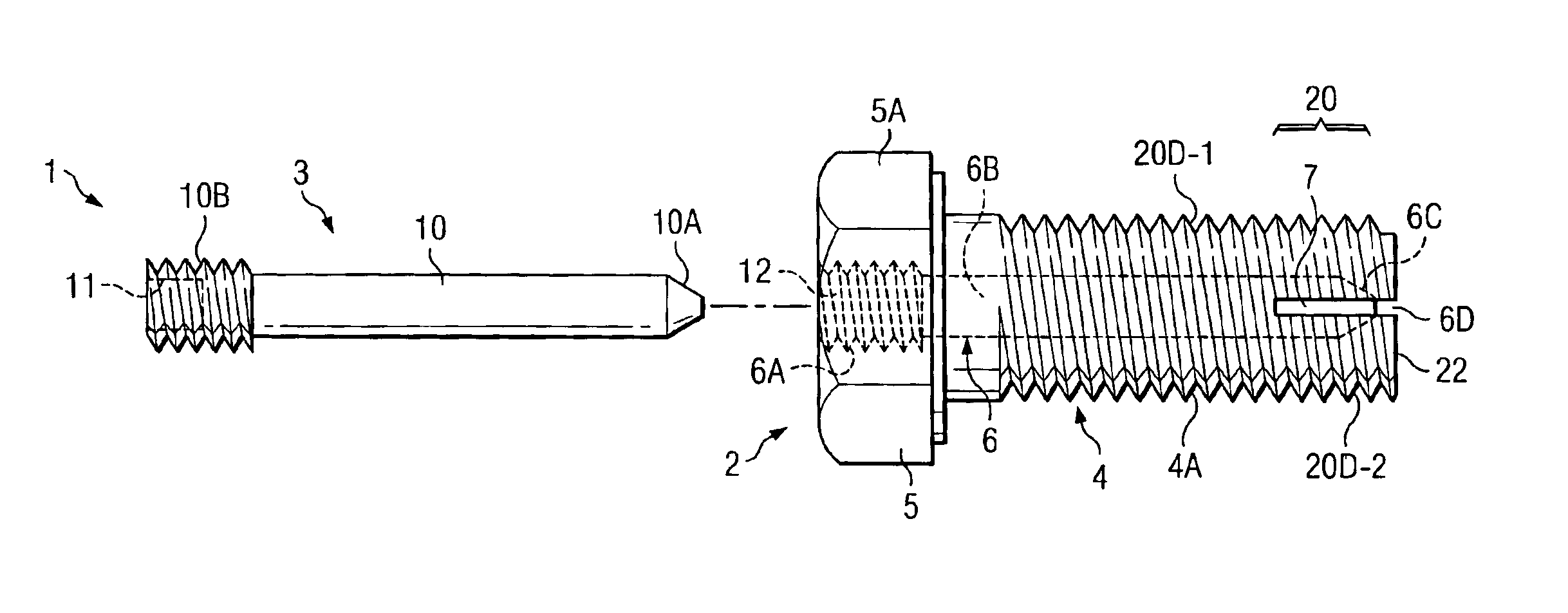
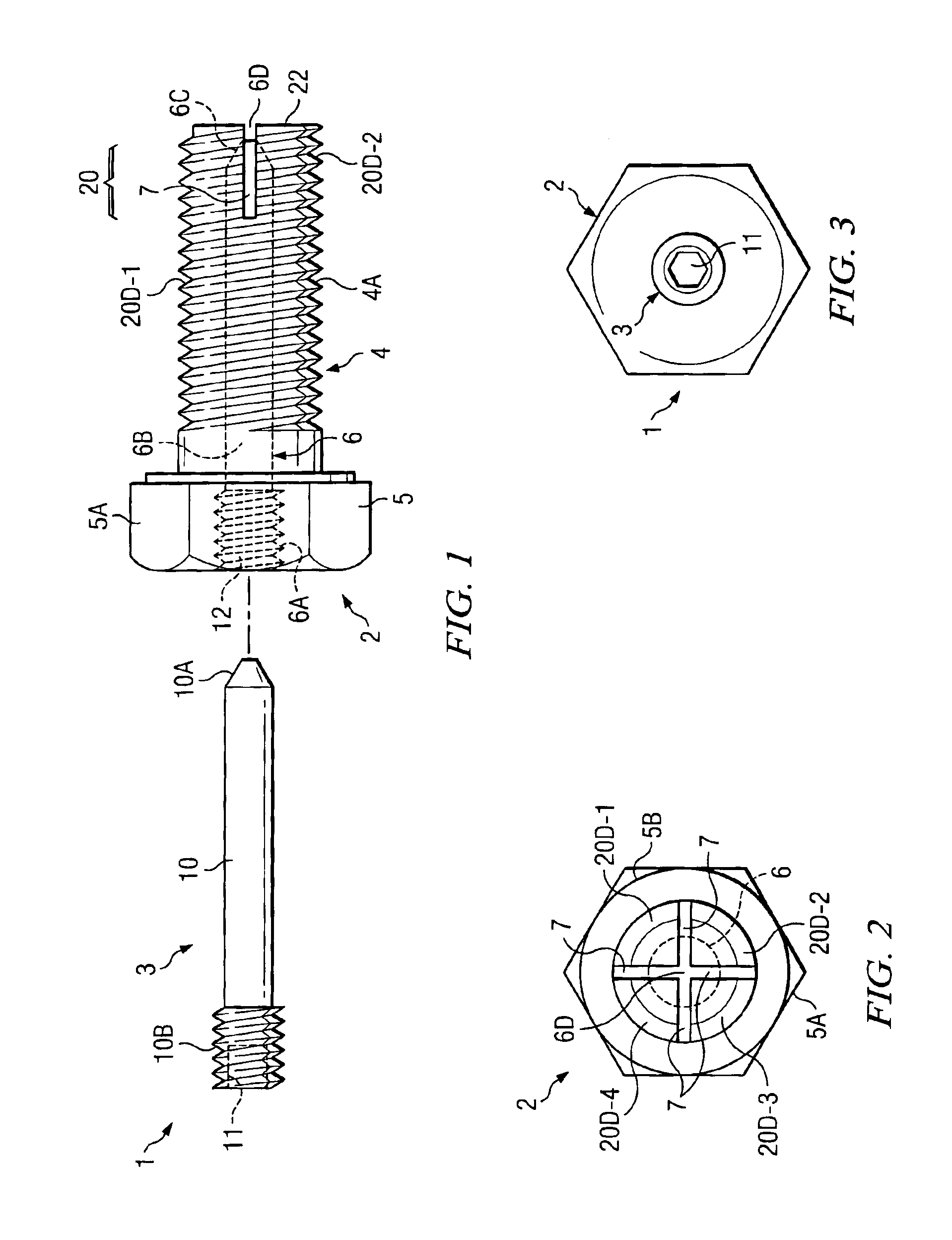
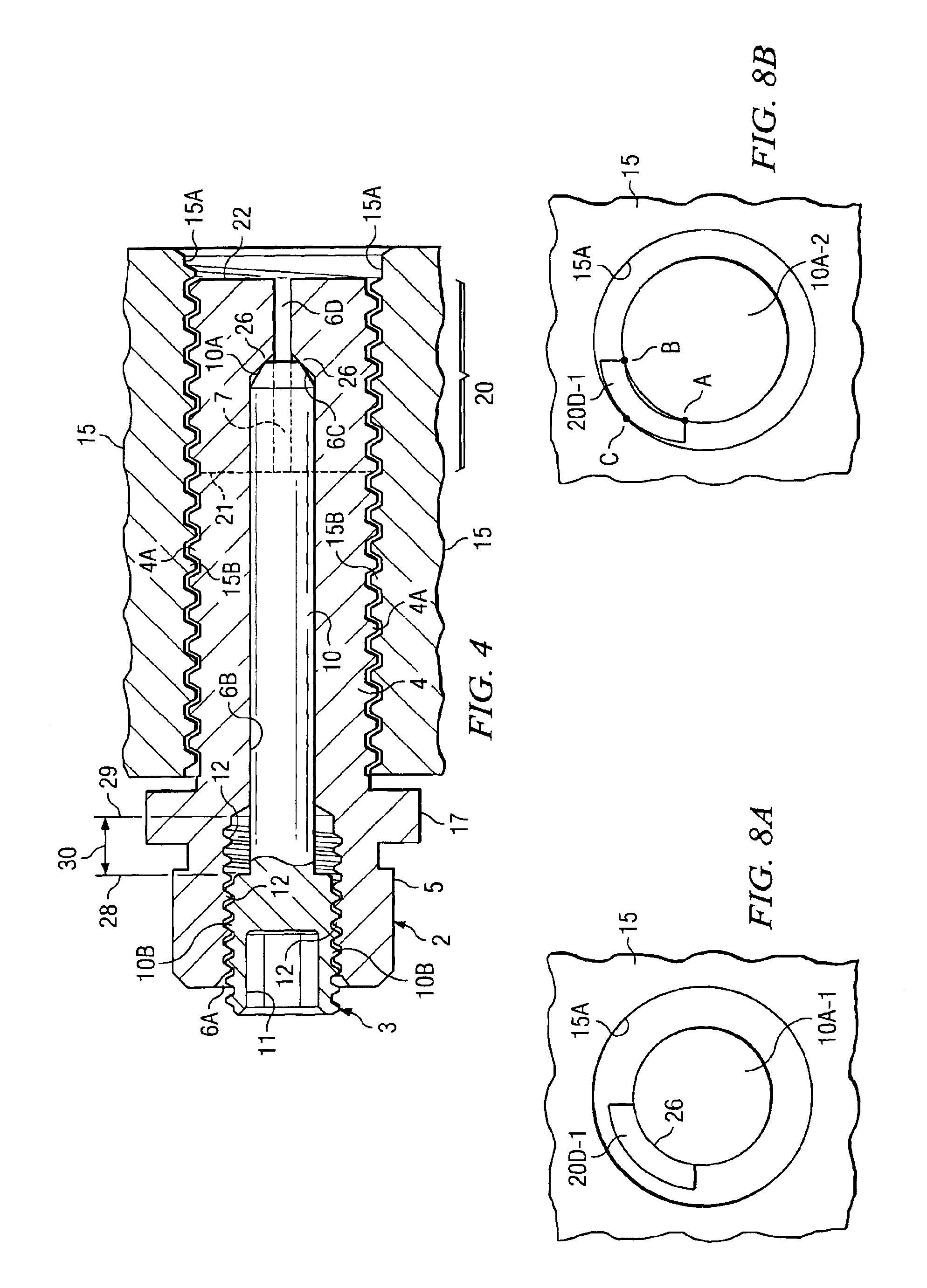
[0032]Referring to FIGS. 1-3, a split bolt and screw set pin assembly 1 includes a hollow split bolt 2 having an axial bolt bore indicated by hidden dashed line 6 and a screw set pin 3 which can be inserted into and tightened into bolt bore 6. Split bolt 2 includes an ordinary bolt head 5 having facets 5A for engagement by a wrench or the like, and also includes a threaded shank 4 through which bolt bore 6 extends. (An annular clamping flange 17 as shown in FIG. 4 can be included as part of bolt head 5.) Shank 4 includes conventional threads 4A on its cylindrical outer surface. A distal end portion 20 of split bolt 2 includes one or more slits 7 to allow expansion of the distal end portion 20 by screw set pin 3, as subsequently explained. Typically, there may be 4 to 8 slits, depending on the size of the fastener.

[0033]Bolt bore 6 includes, from left to right, a proximal cylindrical threaded section 6A having internal threads 12, a cylindrical reduced-diameter midsection 6B continuo...


PUM


Abstract

A self-locking bolt assembly (1) includes a split bolt (2) and a screw set pin (3). The bolt includes a threaded shank (4), an axial bore (6) extending through the shank, the bore (6) including a threaded bore section (6A), a tapered end section (6C), and a bore midsection (6B) between the threaded bore section and the tapered end section. The screw set pin(3) includes a screw section (10B) having threads for engaging the threaded bore section (6A) and a pin shaft (10) having a tapered end section (10A) for engaging the tapered end section (6C) of the bore (6), the pin shaft (10) having a proximal end attached to the screw section (10B). The pin shaft (10) is sufficiently long to ensure that the screw set pin (3) further into the bore (6) without galling threads of the screw section (10B). The tapered end section (10A) of the pin shaft has a taper angle (α) that is less than a taper angle (β) of the tapered end section (6C) of the bore (6) to allow a narrowed end portion of the tapered end section (10A) of the pin shaft (10) to engage a narrowed end portion of the tapered end section (6C) of the bore (6).

Description

[0001]This application claims the benefit of prior filed co-pending U.S. provisional application Ser. No. 60 / 412,358 filed Sep. 21, 2002 entitled “SPLIT LOCK SCREW FASTENER ASSEMBLY” by Patrick William Breslin and Mary Ann Breslin.BACKGROUND OF THE INVENTION[0002]The present invention relates generally to a screw locking assembly including a hollow split stud or split bolt and a screw set-pin that is tightened into the hollow split bolt to lock it tightly into a hole or threaded hole in a medial body. More particularly, the present invention relates to improvements that greatly increase the mechanical advantage between torque applied to the pin setscrew and expansion of a split distal end portion of the bolt and to preventing loosening of the pin setscrew with respect to the split bolt and to preventing loosening of the split bolt with respect to the bolt-receiving hole without galling and causing injury to the threads of either the bolt bore or the pin setscrew as in the prior art....

Claims


Application Information

Patent Timeline
Patent Type & Authority Patents(United States)
IPC IPC(8): F16B39/02F16B13/12F16B13/00F16B35/06F16B35/00F16B35/02F16B39/00F16B35/04
CPCF16B13/126F16B35/02F16B35/041F16B39/023F16B39/028F16B35/06Y10S411/954
Inventor BRESLIN, PATRICK W.BRESLIN, MARY A.
Owner BRESLIN MARY A
Why Eureka
Try Eureka