Locking mechanism for reverse gear shift fork shaft of transmission

A shift fork and locking mechanism technology, applied to mechanical equipment, components with teeth, transmission control, etc., can solve the problem of damage to the canine teeth of the synchronizer ring of the transmission

Active Publication Date: 2017-05-03
EATON INTELLIGENT POWER LIMITED
View PDF5 Cites 0 Cited by
  • Summary
  • Abstract
  • Description
  • Claims
  • Application Information

AI Technical Summary

Problems solved by technology

This can lead to damage to the blocker ring and / or dog teeth of the transmission

Method used


Image

  • Locking mechanism for reverse gear shift fork shaft of transmission
  • Locking mechanism for reverse gear shift fork shaft of transmission
  • Locking mechanism for reverse gear shift fork shaft of transmission

Examples


Embodiment Construction

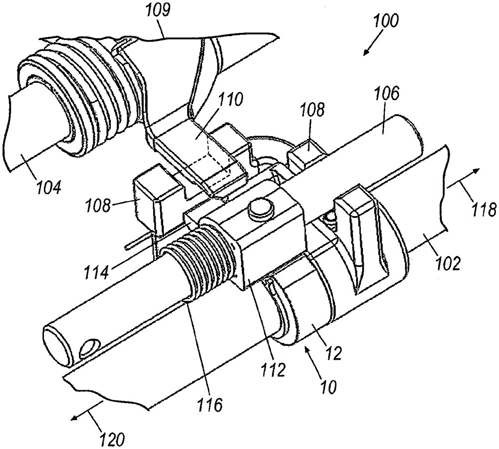
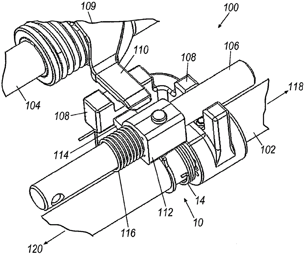
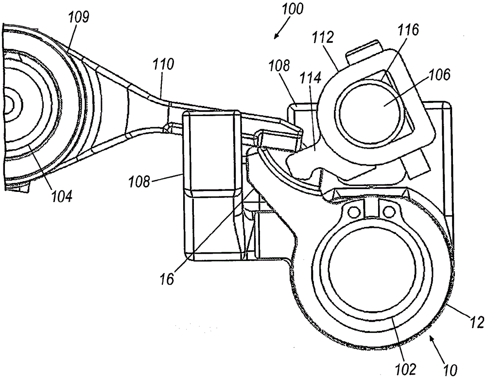
[0026] An exemplary transmission, such as a five-speed transmission, may include a reverse shifter shaft for placing the transmission in a reverse range or another drive range (eg, fifth gear). The shift fork shaft may be configured to move axially in a first direction for a drive range and in a second direction for a reverse range.

[0027] In addition to the reverse shift fork shaft, the example transmission may also include a main shift fork shaft and a reverse inhibitor. The main shift fork shaft may have a fork shaft selector having laterally extending wings configured to selectively engage the reverse shift fork shaft to enable reverse shifting The shift fork shaft can move axially. The reverse inhibitor may be configured to selectively inhibit movement of the reverse shift fork shaft in a second direction toward the reverse range when the reverse shift fork shaft is disengaged from the drive range.

[0028] When disengaging the transmission from a drive range, such as...


PUM


Abstract

An exemplary transmission may have a reverse shifter shaft and a locking mechanism to ensure that the reverse shifter shaft stops in the neutral position when disengaged from another range. The reverse shift fork shaft may be configured to move axially in a first direction to place the transmission in drive and in a second direction to place the transmission in reverse. The transmission may also include a yoke selector configured to engage the reverse shift yoke, and a reverse inhibitor configured to selectively inhibit movement of the reverse yoke in the second direction. An exemplary locking mechanism may include a body and an arm extending from the body. The arm may be configured to contact the reverse inhibitor to substantially inhibit movement of the reverse shifter shaft in the second direction when the reverse shifter shaft is disengaged from the drive range.

Description

[0001] Cross References to Related Applications [0002] This application claims the benefit of US Provisional Application 61 / 736,761, filed December 13, 2012, which is hereby incorporated by reference in its entirety. technical field [0003] The present application relates to a transmission including a reverse shift fork shaft, in particular to a locking mechanism for the reverse shift fork shaft of the transmission. Background technique [0004] Manual compound transmissions are typically located in the driveline adjacent a main drive unit having at least one rotating drive shaft. These compound transmissions typically include a shifter (shift lever) or gear selector that protrudes from the transmission for operator interaction. Compound transmissions may include a rotating slide assembly configured to engage a desired gear set when an operator moves the shifter or range selector. Specifically, in a manual compound transmission, the operator selects the appropriate gear...

Claims


Application Information

Patent Timeline
IPC IPC(8): F16H61/18F16H63/30F16H63/34
CPCF16H61/18F16H63/302F16H63/34F16H2061/185
Inventor C·方塔纳
Owner EATON INTELLIGENT POWER LIMITED
Why Eureka
Try Eureka