Retaining system for a rotor of a dynamoelectric machine

A technology of generator rotor and holding system, applied in electromechanical devices, electrical components, electric components, etc., to achieve the effect of simple structure, high cost, and large diameter

Inactive Publication Date: 2005-04-06
GENERAL ELECTRIC CO
View PDF1 Cites 6 Cited by
  • Summary
  • Abstract
  • Description
  • Claims
  • Application Information

AI Technical Summary

Problems solved by technology

Also, the separation of the ring 16 and the rotor 10 becomes a design challenge for the rotor to reach higher rotational speeds

Method used


Image

  • Retaining system for a rotor of a dynamoelectric machine
  • Retaining system for a rotor of a dynamoelectric machine
  • Retaining system for a rotor of a dynamoelectric machine

Examples


Embodiment Construction

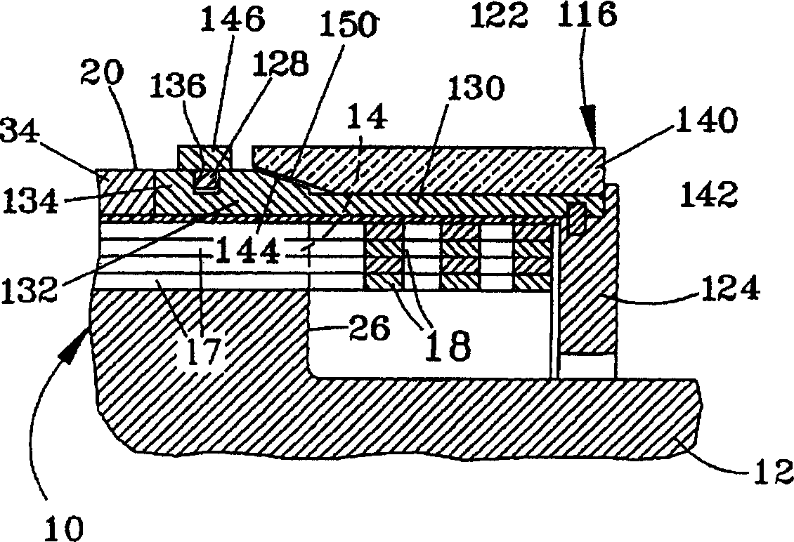
[0035] image 3 and 4 are with figure 1 and 2 The rotor 10 is similar to the partial cross-sectional view of the rotor 10, so the same reference numerals are used here to identify the same or equivalent functional parts of the rotor 10. Likewise, a rotor 10 of this type can also be used in power plants, which are used as the main supplier of high voltage alternating current for distribution or transmission grids, but the rotor 10 can be used in other applications.

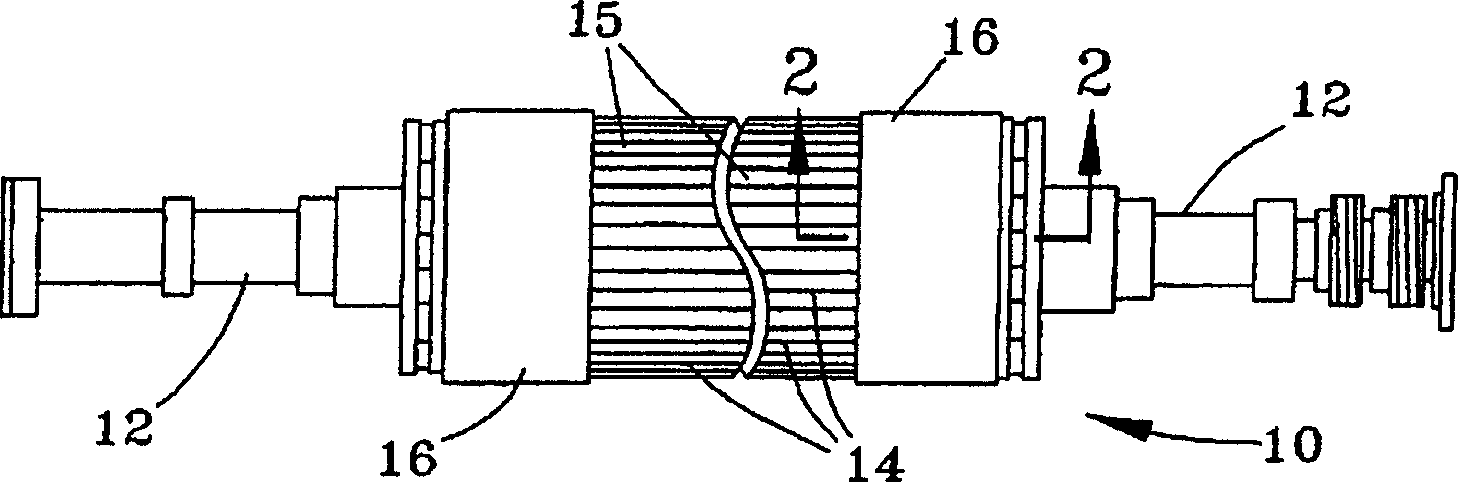
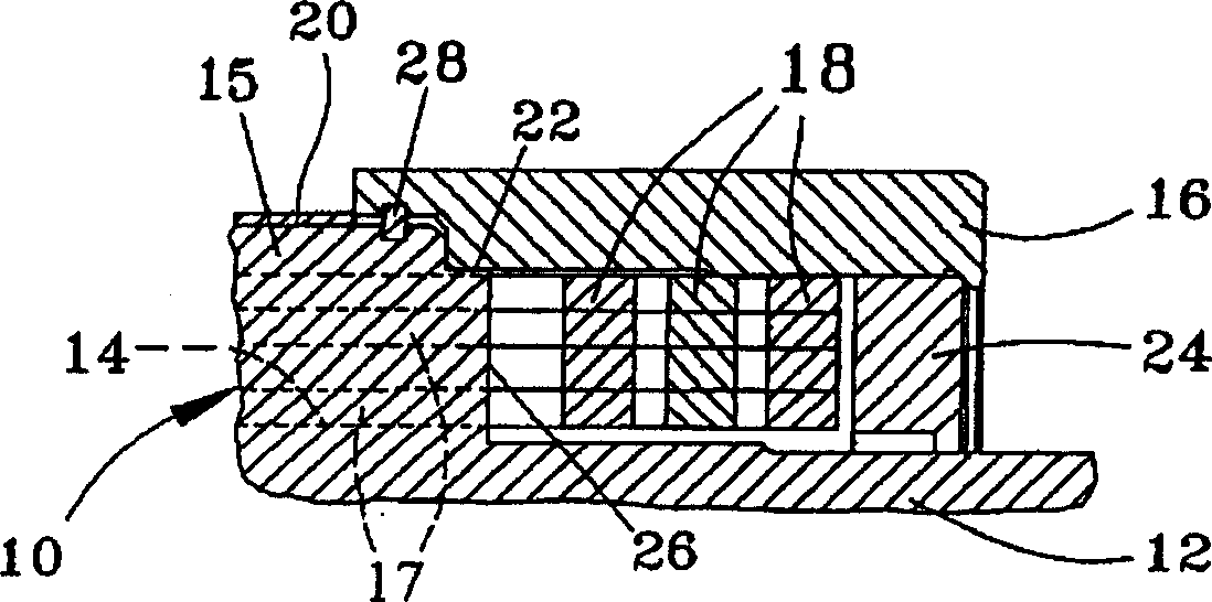
[0036] as figure 1 and 2 Like the rotor 10 in the image 3 The rotor 10 in and 4 has a cylindrical body with an outer surface 20 and radial end faces 26 at opposite ends of the cylindrical body. Furthermore, the slots 14 are on the outer surface 20 of the rotor 10, forming radially extending teeth 15 on the outer surface 20 (FIG. 4). The field winding 17 is located in the slot 14 and protrudes axially from the end face 26 of the rotor 10 . As can best be seen in FIG. 4 , the cross-sectional shape and dimensi...


PUM


Abstract

Provided is a holding system (116) of the end of field winding of the rotor (10) of a dynamoelectric machine. The rotor has an outer circumferential surface (20), a radial end face (26), a slot (14) made in the outer circumferential surface (20) to extend axially, and a field winding (17) placed in the slot. The field winding projects radially from the end face (26) of the rotor and being connected with the end (18) of field winding on the outside of the slot (14). The end of winding is surrounded by a holding system (116) comprising a shield member (130) surrounding the end of winding, and a holder member (140) surrounding the shield member (130). The shield member (130) has a flange (132) received in the slot together with the field winding (17). A securing function (128) engages with the flange to block axial movement of the holding system.

Description

technical field [0001] The present invention relates generally to rotors for electric generators, such as generators for electricity production. More particularly, the present invention relates to a retaining ring supporting field end windings of such a rotor, wherein the retaining ring has a combination that provides a high strength, low density support structure for the end field windings structure. Background technique [0002] Large turbine-driven generators used in electricity production contain a rotor that acts as a source of flux for magnetic flux generated by wire-wound coils supported on the rotor. The rotor rotates within a stator containing a large number of wires which induces an alternating current as the rotor rotates within the stator, creating a rotating magnetic field in the narrow air gap between the stator and rotor. [0003] A rotor 10 for a turbine driven generator is shown in figure 1 and 2 middle. The rotor 10 is generally a large cylindrical bod...

Claims


Application Information

Patent Timeline
Patent Type & Authority Applications(China)
IPC IPC(8): H02K3/46H02K3/51
CPCH02K3/51
Inventor 王瑜乔治·H·加尼米
Owner GENERAL ELECTRIC CO
Why Eureka
Try Eureka