A low-voltage power distribution reactive power compensation cabinet

A low-voltage power distribution and compensation cabinet technology, which is applied in reactive power compensation, reactive power adjustment/elimination/compensation, substation/power distribution device shell, etc., can solve complex structures, substandard waterproofing, and unsatisfactory cooling effects of power cabinets And other issues

Active Publication Date: 2022-03-25
广西金德泰电力安装有限公司
View PDF8 Cites 0 Cited by
  • Summary
  • Abstract
  • Description
  • Claims
  • Application Information

AI Technical Summary

Problems solved by technology

[0002] With the development of the electric power industry, people's lives are inseparable from electric energy, and electric equipment can be seen everywhere in life; while electric power brings convenience to people, there are also hidden safety hazards; electric safety not only considers personal safety, but also needs to be considered The safety of the power equipment itself; many power equipment need to be placed outdoors, and outdoor power cabinets are often required to protect the safety of power equipment; due to the influence of the outdoor natural environment, power cabinets often need to have waterproof and heat dissipation functions; and the existing The heat dissipation effect of some outdoor power cabinets is not ideal, and some equipment is not waterproof; and some qualified equipment has the characteristics of complex structure, high production and use costs, so the existing equipment needs to be improved and upgraded

Method used


Image

  • A low-voltage power distribution reactive power compensation cabinet
  • A low-voltage power distribution reactive power compensation cabinet
  • A low-voltage power distribution reactive power compensation cabinet

Examples


Embodiment Construction

[0018] The following will clearly and completely describe the technical solutions in the embodiments of the present invention with reference to the accompanying drawings in the embodiments of the present invention. Obviously, the described embodiments are only some, not all, embodiments of the present invention. Based on the embodiments of the present invention, all other embodiments obtained by persons of ordinary skill in the art without making creative efforts belong to the protection scope of the present invention.

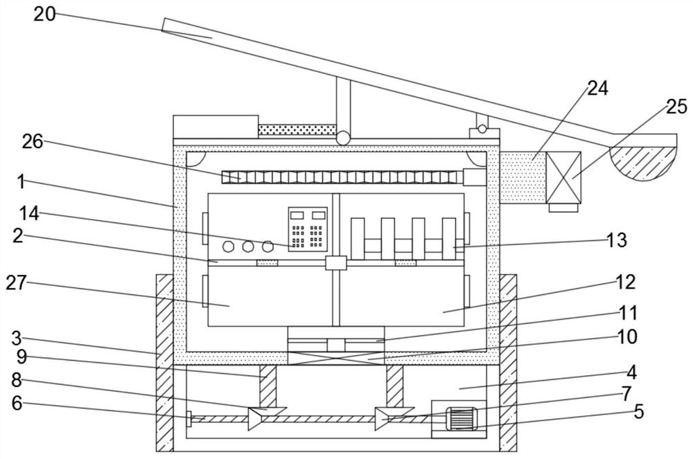
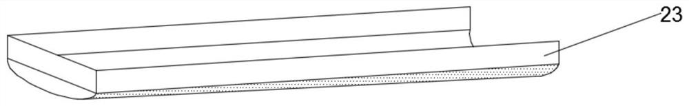
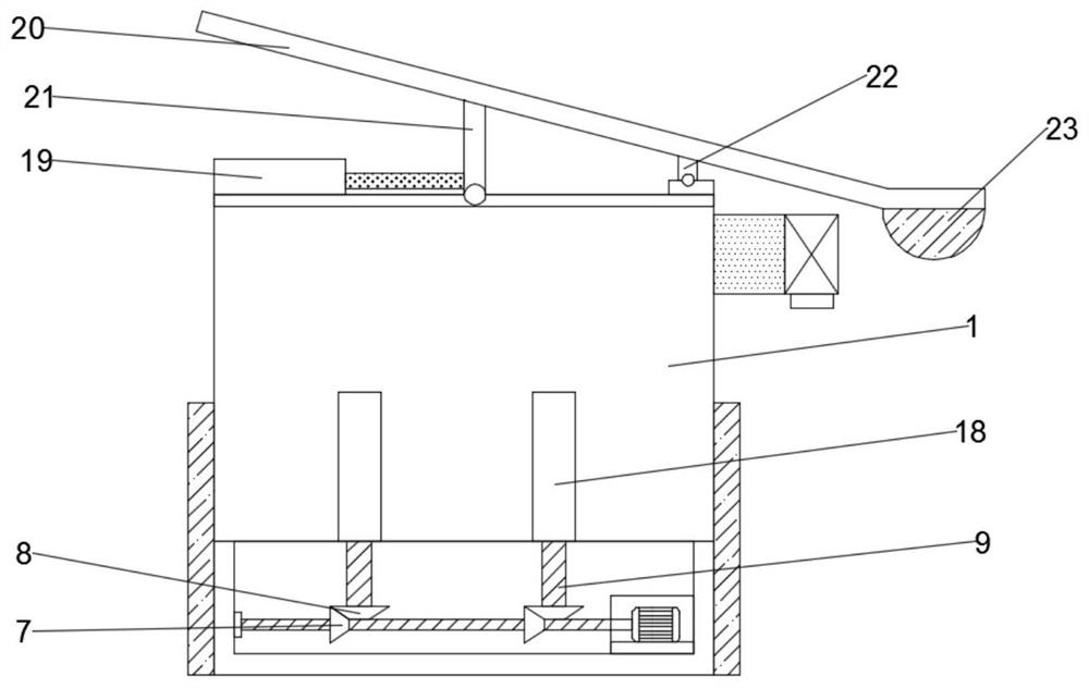
[0019] see Figure 1-5 , in an embodiment of the present invention, a low-voltage power distribution reactive power compensation cabinet includes a cabinet body 1, an inner cavity 2, a limit plate 3, a drive cavity 4 and a rain shield 20, and the inner cavity 2 is set inside the cabinet body 1 , the bottom of the cabinet body 1 is slidably connected to the limit plate 3, and the upper surface of the cabinet body 1 is provided with a rain shield 20; the top of ...


PUM


Abstract

The invention discloses a reactive power compensation cabinet for low-voltage power distribution, which comprises a cabinet body, an inner cavity, a limit plate, a drive cavity and a rain-shielding plate. The inner cavity is arranged inside the cabinet body, and the lower part of the cabinet body is slidingly connected to limit the position. The upper surface of the cabinet body is provided with a rain shield; the top of the inner cavity is provided with a main control panel and a capacitor box, and the right side of the inner surface of the limiting plate is fixed with a welding drive motor, and the drive motor is a forward and reverse motor , the left output shaft of the drive motor is fixedly welded to the first rotating shaft, and the end of the first rotating shaft away from the driving motor is connected to the side wall of the limiting plate by rotation; the present invention can change the height of the cabinet with reasonable design, effectively avoid the invasion of rainwater; thereby prolonging the service life of the cabinet; and can realize the control of the compensation circuit to ensure that the compensation circuit works within the normal range, so that the compensation circuit can more accurately realize the adjustment of the power, ensuring Electricity electricity safety.

Description

technical field [0001] The invention relates to the technical field of electric equipment, in particular to a reactive power compensation cabinet for low-voltage power distribution. Background technique [0002] With the development of the electric power industry, people's lives are inseparable from electric energy, and electric equipment can be seen everywhere in life; while electric power brings convenience to people, there are also hidden safety hazards; electric safety not only considers personal safety, but also needs to be considered The safety of the power equipment itself; many power equipment need to be placed outdoors, and outdoor power cabinets are often required to protect the safety of power equipment; due to the influence of the outdoor natural environment, power cabinets often need to have waterproof and heat dissipation functions; and the existing The heat dissipation effect of some outdoor power cabinets is not ideal, and some equipment is not waterproof; an...

Claims


Application Information

Patent Timeline
Patent Type & Authority Patents(China)
IPC IPC(8): H02J3/18H02B1/56H02B1/28H02B1/32
CPCH02B1/28H02B1/32H02B1/565H02J3/18Y02E40/30
Inventor 陈翔宇
Owner 广西金德泰电力安装有限公司
Why Eureka
Try Eureka