Liquid crystal display device

A liquid crystal display device and display panel technology, which is applied to instruments, nonlinear optics, optics, etc., can solve problems such as affecting the driver's observation of the vehicle display device, difficult to meet the asymmetric viewing angle requirements, affecting the driver's driving safety, etc. The effect of improving display quality, improving display quality, improving driving safety

Inactive Publication Date: 2019-04-02
SHANGHAI TIANMA MICRO ELECTRONICS CO LTD
View PDF7 Cites 0 Cited by
  • Summary
  • Abstract
  • Description
  • Claims
  • Application Information

AI Technical Summary

Problems solved by technology

[0003] With the rapid development of the liquid crystal display industry, the application of various liquid crystal display panels continues to increase. At present, the viewing angle design of display devices on the market is mainly symmetrical, which is difficult to meet the requirements of asymmetrical viewing angles. Vehicle-mounted liquid crystal display devices are used in different The loading position and different angles of view, the visual effects and lighting parameters are quite different, and the display device is generally installed in the central control position of the vehicle. Compared with the driver's position, it is on the driver's side. When the driver observes the display device, the general angle of view is not Viewed from the front of the display device, it is easy to cause the resolution of the driver's perspective to be too low, so it greatly affects the driver's observation of the vehicle display device, and therefore directly affects the driver's driving safety.

Method used


Image

  • Liquid crystal display device
  • Liquid crystal display device
  • Liquid crystal display device

Examples


no. 1 example

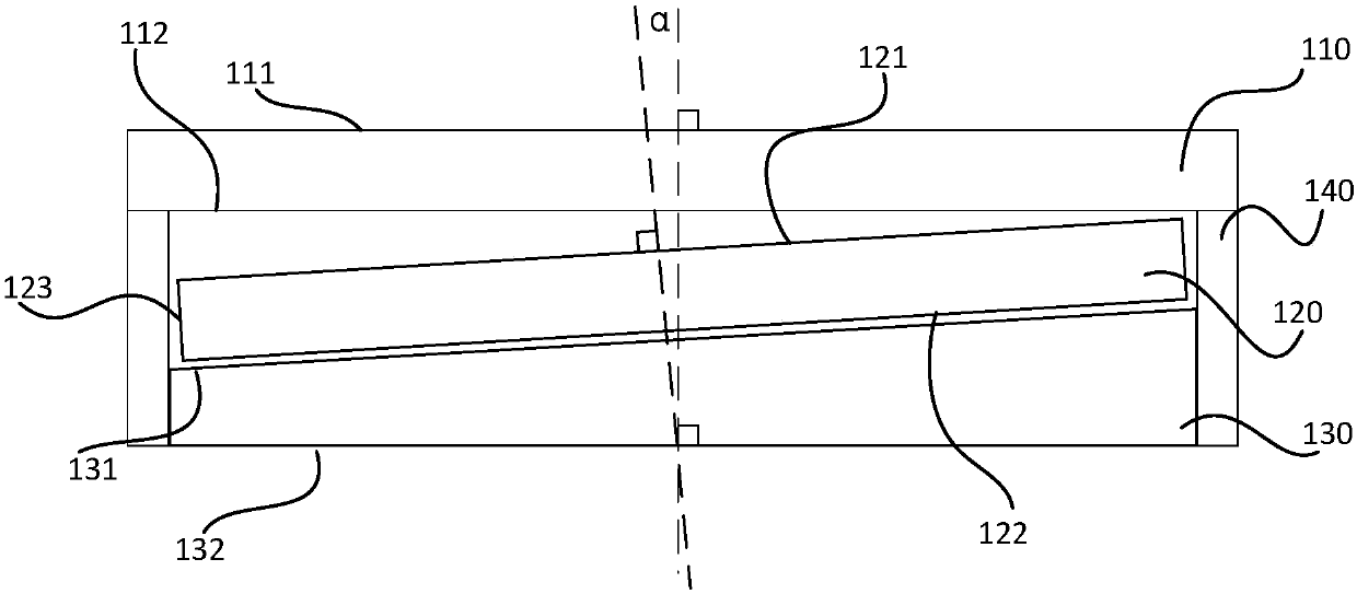
[0017] This embodiment provides a liquid crystal display device, such as figure 1 as shown, figure 1 A schematic diagram of a liquid crystal display device provided in the first embodiment of the present invention; the liquid crystal display device includes: a backlight module and a display panel 110, wherein the backlight module includes an optical component 120 and a bottom plate 130, in an optional embodiment, The optical assembly 120 may include a reflection sheet, a light guide plate, a diffusion sheet, and a prism sheet; the bottom plate 130 includes a first side 131 of the bottom plate facing the optical assembly 120 and a second side 132 of the bottom plate facing away from the optical assembly 120; The upper surface 111 of the display panel of the assembly 120 and the lower surface 112 of the display panel facing the optical assembly 120; A plurality of side surfaces 123 of the optical component on the bottom surface 122 of the component, in this embodiment, the side...

no. 2 example

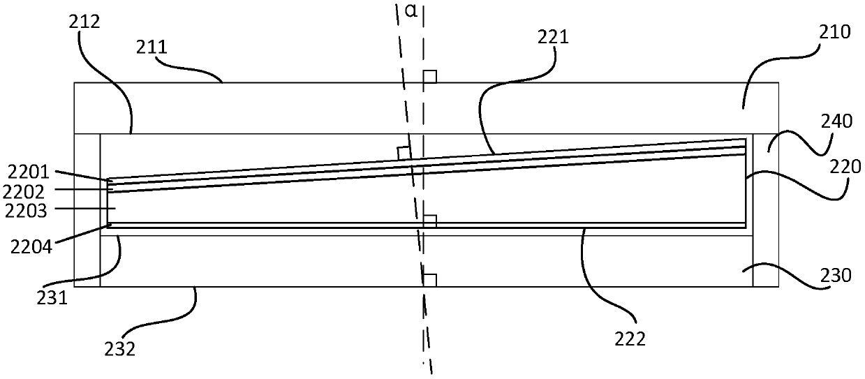
[0024] This embodiment provides a liquid crystal display device, such as figure 2 as shown, figure 2 A schematic diagram of a liquid crystal display device provided for the second embodiment of the present invention; the liquid crystal display device includes: a backlight module and a display panel 210, wherein the backlight module includes an optical assembly 220 and a bottom plate 230, in an optional embodiment, The optical assembly 220 may include a reflection sheet 2204, a light guide plate 2203, a diffusion sheet 2202 and a prism sheet 2201; the base plate 230 includes a base plate first side 231 facing the optical assembly 220 and a base plate second side 232 facing away from the optical assembly 220; the display panel 210 Comprising an upper surface 211 of the display panel facing away from the optical assembly 220 and a lower surface 212 of the display panel facing the optical assembly 220; , in this embodiment, the light guide plate includes the upper surface of th...

no. 3 example

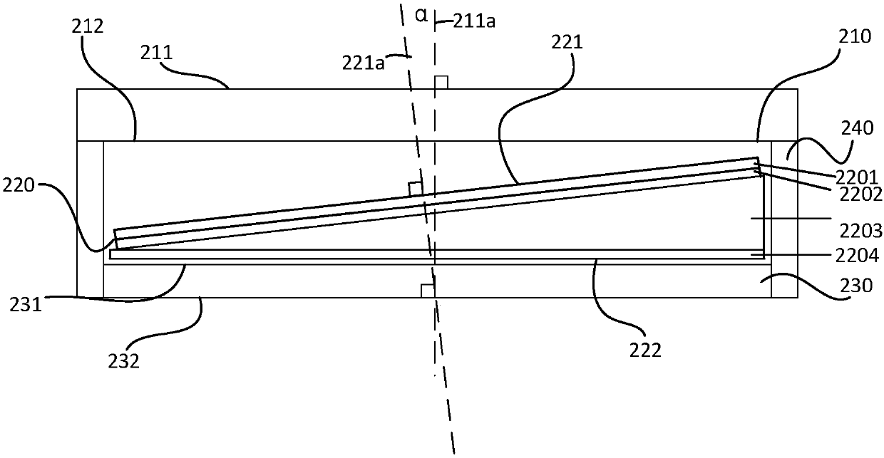
[0033] This embodiment provides a liquid crystal display device, such as Figure 5 as shown, Figure 5 A schematic diagram of a liquid crystal display device provided in the third embodiment of the present invention; the liquid crystal display device includes: a backlight module and a display panel 110, wherein the backlight module includes an optical component 320 and a bottom plate 330, in an optional embodiment, The optical assembly 320 may include a reflection sheet, a light guide plate, a diffusion sheet, and a prism sheet; the bottom plate 330 includes a bottom plate first side 331 facing the optical assembly 320 and a bottom plate second side 332 facing away from the optical assembly 320; the display panel 310 includes a rear-facing optical The upper surface 311 of the display panel of the assembly 320 and the lower surface 312 of the display panel facing the optical assembly 320; The light refraction part 320a is included, and the light refraction part 320a is located...


PUM


Abstract

The invention provides a liquid crystal display device, comprising a backlight module and a display panel. The backlight module comprises an optical assembly and a bottom plate. The optical assembly comprises a reflection piece, a light guide plate, a scattering piece and a prismatic lens. The bottom plate comprises a bottom plate first side face facing the optical assembly and a bottom plate second side face facing away from the optical assembly. The display panel comprises a display panel upper surface facing away from the optical assembly and a display panel lower surface facing the opticalassembly. The optical assembly comprises an optical assembly bottom surface facing the bottom plate first side face, an optical assembly top surface facing the display panel and a plurality of optical assembly side faces perpendicular to the optical assembly bottom surface. The normal direction of the bottom plate second side face is parallel to the normal direction of the display panel lower surface, and the normal direction of the optical assembly top surface intersects the normal direction of the display panel lower surface. The liquid crystal display device can improve the driving safetyof the driver.

Description

technical field [0001] The invention relates to the field of vehicle displays, in particular to a liquid crystal display device. Background technique [0002] With the continuous improvement of people's living standards, the number of private cars is increasing day by day, and various supporting equipment for private cars are becoming more and more complete, allowing people to enjoy different pleasures during travel. Among them, car TVs are becoming more and more popular. . [0003] With the rapid development of the liquid crystal display industry, the application of various liquid crystal display panels continues to increase. At present, the viewing angle design of display devices on the market is mainly symmetrical, which is difficult to meet the requirements of asymmetrical viewing angles. Vehicle-mounted liquid crystal display devices are used in different The loading position and different angles of view, visual effects, and lighting parameters are quite different, and...

Claims


Application Information

Patent Timeline
Patent Type & Authority Applications(China)
IPC IPC(8): G02F1/13357
CPCG02F1/1336G02F1/133605G02F1/133606G02F1/133607
Inventor 姚永利
Owner SHANGHAI TIANMA MICRO ELECTRONICS CO LTD
Why Eureka
Try Eureka