Exhibit clamping equipment capable of increasing viewing angle through right-angle rotation

A technology of viewing angle and clamping equipment, which is applied in the direction of display stands, display hangers, display shelves, etc., can solve the problems of limited display range of fixed axis rotation of exhibits and low efficiency of exhibit loading and unloading, so as to facilitate clamping of exhibits and improve loading and unloading Efficiency, the effect of improving practicality

Inactive Publication Date: 2021-12-28
李万军
View PDF0 Cites 0 Cited by
  • Summary
  • Abstract
  • Description
  • Claims
  • Application Information

AI Technical Summary

Problems solved by technology

[0005] Aiming at the deficiencies of the prior art, the present invention provides an exhibit clamping device that rotates at right angles to increase the viewing angle. It has the advantages of changing the viewing angle of exhibits in a circular rotation cycle and facilitating clamping to improve the loading and unloading efficiency of exhibits. Issues of limited scope and inefficient loading and unloading of exhibits

Method used


Image

  • Exhibit clamping equipment capable of increasing viewing angle through right-angle rotation
  • Exhibit clamping equipment capable of increasing viewing angle through right-angle rotation
  • Exhibit clamping equipment capable of increasing viewing angle through right-angle rotation

Examples


Embodiment 1

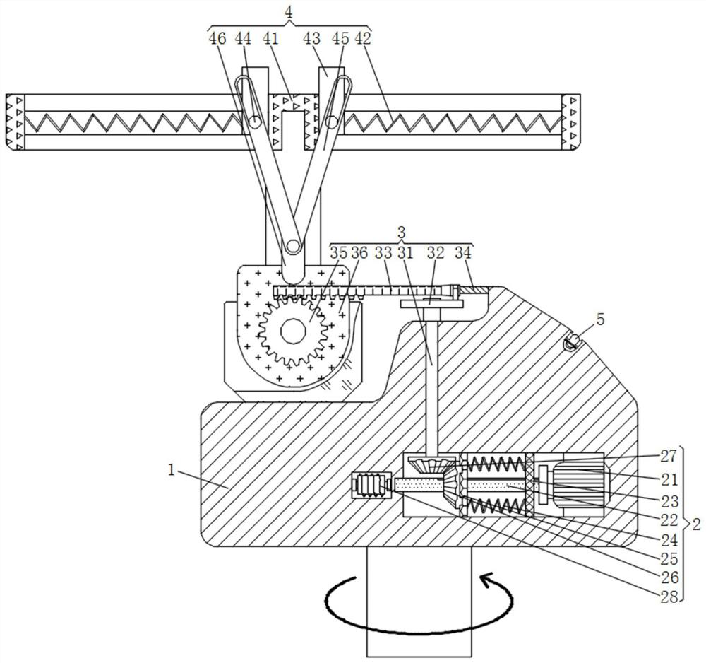
[0026] See figure 1 , 3 , 4 and 5. A quarter turn increasing the angle of view exhibits clamping device includes a base 1, the bottom of the base 1 is fixedly connected with the power mechanism 2, a power mechanism 2 comprises a motor 21, a shaft 22, fixed disk 23, a spring 24, the movable disk 25, a bevel gear 26, two bevel gear 27, the electromagnet 28, the output end of the motor 21 is fixedly connected with a rotary shaft 22, a left side peripheral rotary shaft 22 is fixedly connected with a fixing plate 23, the fixed plate 23 left attached a mobile disk 24 by a resilient spring 25, the movable disk 25 is connected with the left side of a card 26, bevel gear engaging the upper bevel gear 26 is connected to a two bevel gear 27, a rotary shaft 22 disposed on the left side are the electromagnet 28, the motor 21 is fixedly connected at the bottom right end of the inner wall of the base 1, a rotational shaft 22 is connected at the bottom of the base 1, the inner wall of the fixed p...

Embodiment 2

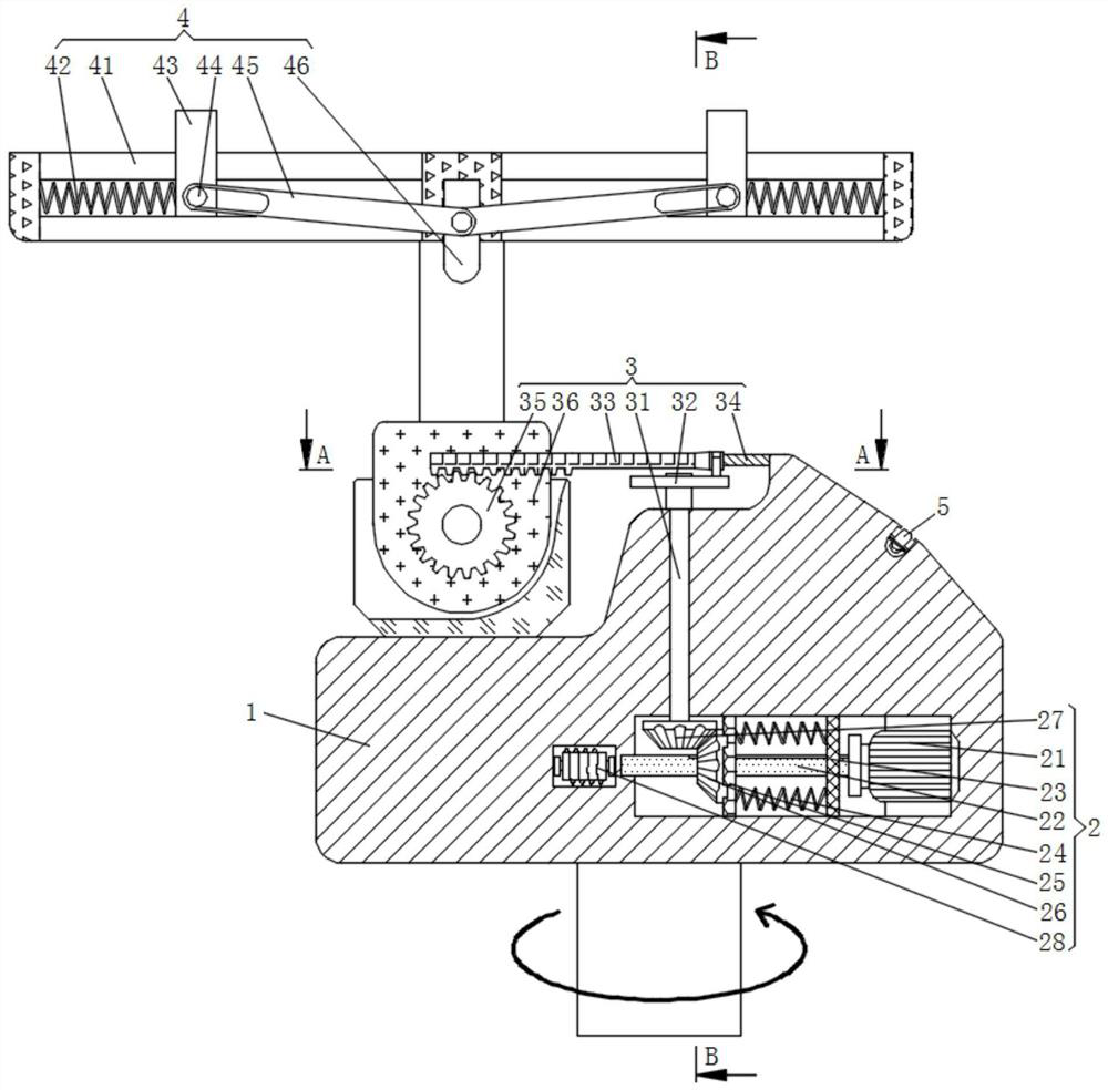
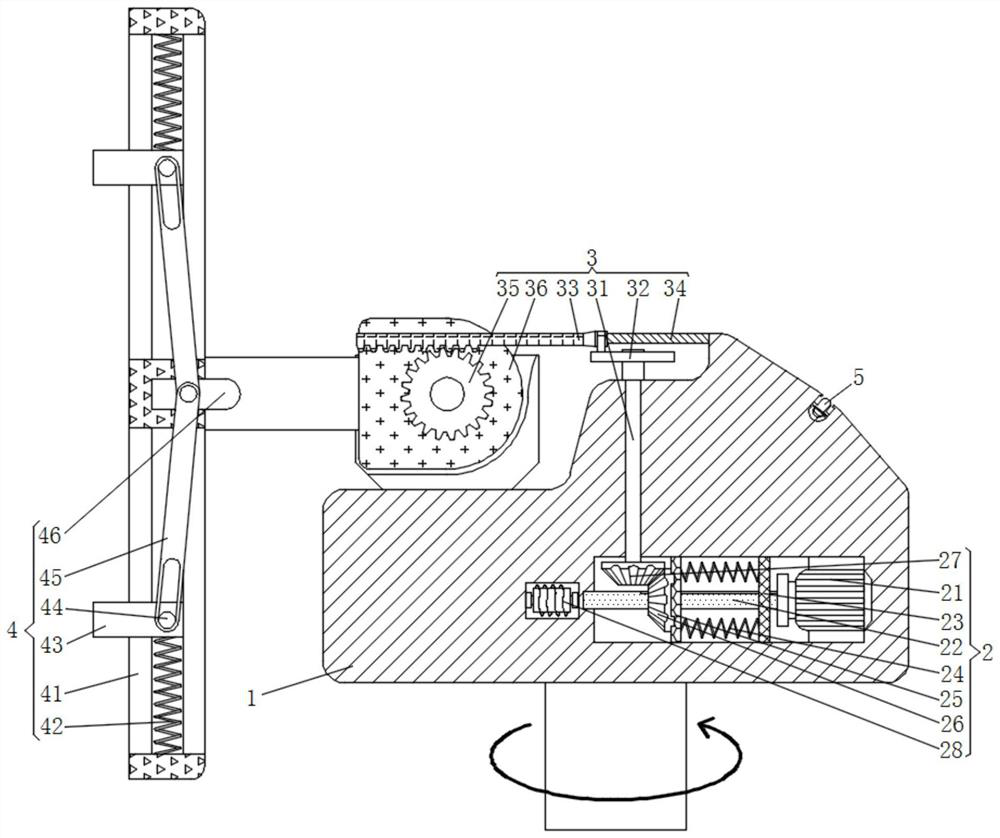
[0028] See figure 1 and 2 A quarter turn increasing the angle of view exhibits clamping device includes a base 1, the bottom of the base 1 is fixedly connected with the power mechanism 2, the top of the base 1 is rotatably connected to the adjustment mechanism 3, above the base 1 is provided with a fixing means 4, 4 includes a stopper mechanism fixing frame 41, two springs 42, clamp block 43, block 44 slot, slotted rod 45, the pull block 46, both ends of the left and right inner walls of the stopper frame 41 is connected to a clamp block 43 by two elastic spring 42, interposed front end block 43 is connected via a transmission channel block 44 has a slotted rod 45, the bottom end of the rod groove 45 hinged pull block 46, the stopper frame 41 is fixedly connected to the top of the regulator, the hollow interior of the stopper frame 41 of the seat 36, stopper internal frame 41 is connected to the stopper clamp block 43, clamp block 43 is fixed to the front end of a groove connector...

Embodiment 3

[0030] See Figure 1-5, A right angle to increase the exhibit clamping apparatus of the viewing angle, including the base 1, the bottom fixed connection of the base 1, the power mechanism 2 includes a motor 21, a shaft one 22, a fixed disk 23, a spring 24, a movable disk 25, tapered teeth 26, tapered teeth 27, electromagnet 28, the output of the motor 21 fixed to the shaft shaft 12, the left side of the rotary shaft 122, the fixed disk 23, the left side of the fixed disk 23 through the spring A 24 elastic connection has a movable magnetic disk 25, the left card of the movable disk 25 is connected to the tapered teeth 26, and the upper side engagement of the tapered teeth 26 has a cone 27, and the left side of the rotary shaft one 22 is provided with an electromagnet 28, The motor 21 is fixedly attached to the right end of the bottom inner wall of the base 1, and the rotating shaft 122 is rotated to be attached to the bottom of the base 1, the inner wall of the fixing disk 23 and th...


PUM


Abstract

The invention relates to the technical field of conference exhibition equipment, and discloses exhibit clamping equipment capable of increasing the viewing angle through right-angle rotation. The exhibit clamping equipment comprises a base, the bottom of the base is fixedly connected with a power mechanism, the top of the base is rotatably connected with an adjusting mechanism, a fixing mechanism is arranged above the base, and the right end of the top of the base is elastically connected with a control contact. According to the exhibit clamping equipment capable of increasing the viewing angle through right-angle rotation, meshing of a first bevel gear and a second bevel gear is controlled by changing the position of a movable magnetic disc, a limiting disc rotates to enable a gear frame to reciprocate under limiting of a limiting rod, meshing of a first gear is matched, and the effect of circularly changing the viewing angle of an exhibit through right-angle rotation is achieved; groove rods are closed by upwardly pushing a pull block, and under the limiting of the groove block and the inner wall of the limiting frame, the clamping blocks move back to back to increase the clamping width; and after an exhibit is placed between the clamping blocks, the pull block is put down, so that the effect of conveniently clamping the exhibit is achieved, and the loading and unloading efficiency of the exhibit is improved.

Description

Technical field [0001] Technical Field The present invention relates to apparatus and Exhibition Conference, particularly as a quarter-turn to increase the viewing angle exhibits clamping device. Background technique [0002] Exhibition refers to short meetings, exhibitions, events and other collective commercial or non-commercial activities, the exhibition is through propaganda, the exhibition will be interested in the content of the crowd at the same time concentrated in the same place, directing the crowd exhibitions related items visit, typically used when booth exhibits in the exhibition, for people to visit, but only existing booth rotating display, resulting in the exhibits on the stand only on one axis of rotation, does not have a tilt angle of the viewer when you want to watch his picture, it is necessary to elevate or squat observation viewing angle exhibits increased, reducing the usefulness of the device, and when the existing booth in order to prevent display exhibit...

Claims


Application Information

Patent Timeline
Patent Type & Authority Applications(China)
IPC IPC(8): A47F5/12A47F5/02A47F7/00
CPCA47F5/12A47F5/02A47F7/0021
Inventor 李万军
Owner 李万军
Why Eureka
Try Eureka