Image display apparatus

a technology of image display and display screen, which is applied in the direction of instruments, optics, static indicating devices, etc., can solve the problem of increasing the size of the entire apparatus, and achieve the effect of small (thin) structure and easy widening the view angle of an observed imag

Inactive Publication Date: 2007-09-06
CANON KK
View PDF3 Cites 9 Cited by
  • Summary
  • Abstract
  • Description
  • Claims
  • Application Information

AI Technical Summary

Benefits of technology

[0010]It is an object of the present invention to provide an image display apparatus capable of easily widening a view angle of an observed image with a small (thin) structure in general.
[0013]According to the present invention, an image display apparatus is provided which is capable of easily widening a view angle of an observer while reducing the size of the apparatus to be small (thin) in general.

Problems solved by technology

The optical system in which intermediate image is formed in the optical path to widen the view angle requires a large number of components and a long optical path length, so the size of the entire apparatus tends to become larger.

Method used


Image

  • Image display apparatus
  • Image display apparatus
  • Image display apparatus

Examples


embodiment 1

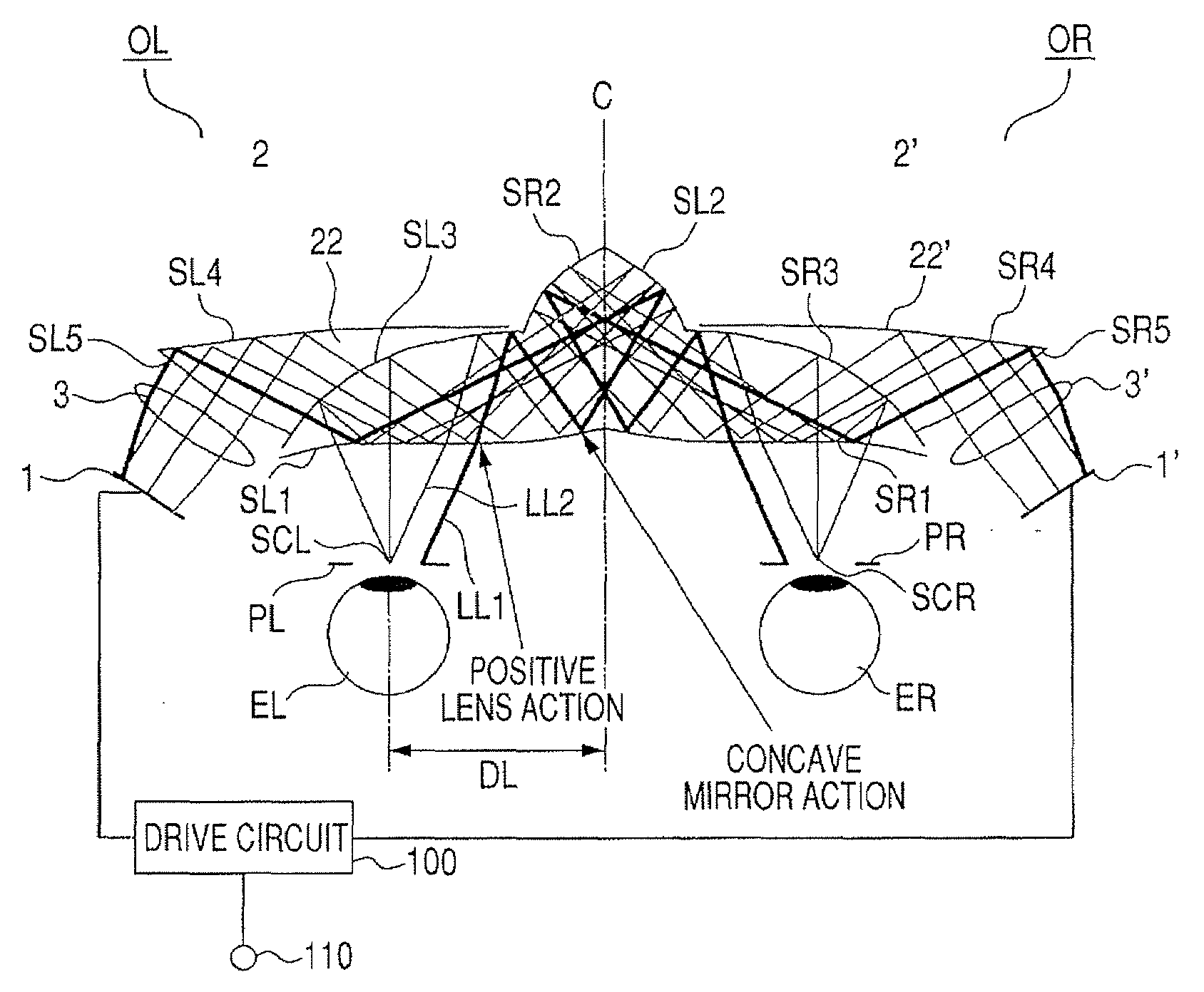
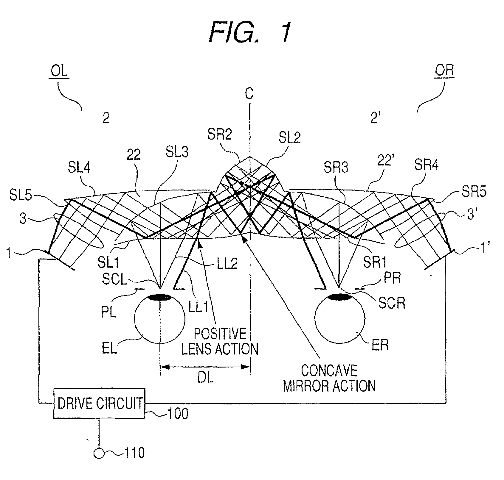
[0023]FIG. 1 illustrates a structure of the present invention in a case where the present invention is applied to a head-mount display (HMD) and schematically illustrates the HMD viewed from the top.

[0024]A prism (optical device) 21 is shared by an optical system for left and right eyes. In the prism 21, surfaces SL1 (SLa), SL2, SL3, SR1 (SLa), SR 2, and SR3 are formed on a medium having a refractive index larger than 1.

[0025]A prism 22 is cemented onto the surface SL3. In the prism 22, in addition to the surface SL3 shared with the prism 21, surfaces SL4 and SL5 are formed on a medium having a refractive index larger than 1.

[0026]A prism 22′ is cemented onto the surface SR3. In the prism 22′, in addition to the surface SR3 shared with the prism 21, surfaces SR4 and SR5 are formed on a medium having a refractive index larger than 1.

[0027]An image forming element 1 for a left eye EL is constituted by a liquid crystal display (LCD).

[0028]A prism part 2 which includes a curved decenter...

second embodiment

[0057]FIG. 4 illustrates a structure of the present invention in a case where the present invention is applied to a head-mount display (HMD) and schematically illustrates the HMD viewed from the top.

[0058]A second embodiment is mainly different from the first embodiment in that a lens (optical element) 4 having a positive refractive power which forms a part of the left eye optical system OL is disposed between the prism 21 and the left exit pupil PL, and a lens (optical element) 4′ having the positive refractive power which forms a part of the right optical system OR is disposed between the prism 21 and the right exit pupil PR. Other structures are similar to those of the first embodiment. Components identical with those according to the first embodiment are denoted by the same reference symbols and explanations thereof are omitted.

[0059]The optical paths according to the second embodiment are also symmetrical with respect to the plane C, so a description is made of only the left ey...

third embodiment

[0066]FIG. 5 illustrates a structure of the present invention in a case where the present invention is applied to a head-mount display (HMD) and schematically illustrates the HMD viewed from the top.

[0067]A third embodiment is mainly different from the second embodiment in that hollow mirrors 23 and 24 formed of a plurality of reflecting surfaces are used instead of the prism 21. Other structures are similar to those of the second embodiment. Components identical with those according to the second embodiment are denoted by the same reference symbols and explanations thereof are omitted.

[0068]Optical paths according to the third embodiment are also symmetrical with respect to the plane C, so a description is made of only the left eye optical system OL. A light beam emitted from the LCD 1 disposed on the left eye EL (not illustrated) side of the plane C is condensed by the lens 3, and is guided to the transparent surface SL5 of the prism 22. The light beam made incident on the prism 2...


PUM


Abstract

An image display apparatus having a wide view angle of an observed image with a small (thin) structure, which includes: two image forming elements; and an optical system guiding a beam from the image forming elements to two observation areas, wherein the system includes curved reflecting surfaces, and is symmetrical about a symmetry plane intermediate between the observation areas, in which a beam from the image forming element on a side of the symmetry plane is reflected on a curved reflecting surface on the side, reflected on a curved reflecting surface on the other side, is reflected on the surface on the side, and transmits a surface SLa to be guided to the observation area on the side; and an area, in the surface Sla, which a beam LLa traveling along an optical path closest to the symmetry plane transmits, has a shape having positive refractive power.

Description

BACKGROUND OF THE INVENTION[0001]1. Field of the Invention[0002]The present invention relates to an image display apparatus for displaying an image, which is formed on an image forming element such as a liquid crystal display element, to an observer via an optical system, and more particularly, to an image display apparatus suitable for a head-mount display (HMD).[0003]2. Description of the Related Art[0004]An image display apparatus such as a head-mount display (HMD) is desired to have presence enhanced by widening a view angle of an observed image, and to be miniaturized and lightened in general in order to be mounted on a head of a user. In particular, when a weight balance and an appearance of the entire apparatus are taken into account, it is desirable that the image display apparatus have a small thickness in a visual axis direction (front direction) of an observer.[0005]In order to widen the view angle using a small liquid crystal panel, it is preferable to form an intermedia...

Claims


Application Information

Patent Timeline
Patent Type & Authority Applications(United States)
IPC IPC(8): G02B27/14
CPCG02B2027/0123G02B27/0172
Inventor INOGUCHI, KAZUTAKAMATSUNAGA, MOTOMI
Owner CANON KK
Why Eureka
Try Eureka