3D display apparatus

A display device, 3D technology, applied in the direction of optics, instruments, electrical components, etc., can solve the problems of narrow viewing angle and low display resolution, achieve the effect of improving viewing angle, improving display resolution, and solving narrow viewing angle

Active Publication Date: 2015-11-25
TCL CHINA STAR OPTOELECTRONICS TECH CO LTD
View PDF1 Cites 10 Cited by
  • Summary
  • Abstract
  • Description
  • Claims
  • Application Information

AI Technical Summary

Problems solved by technology

[0006] The object of the present invention is to provide a 3D display device with a higher display resolution and a wider viewing angle; to solve the technical problems of the existing 3D display devices with a lower display resolution and a narrower viewing angle

Method used


Image

  • 3D display apparatus
  • 3D display apparatus
  • 3D display apparatus

Examples


Embodiment Construction

[0031] The following descriptions of the various embodiments refer to the accompanying drawings to illustrate specific embodiments in which the present invention can be practiced. The directional terms mentioned in the present invention, such as "up", "down", "front", "back", "left", "right", "inside", "outside", "side", etc., are for reference only The orientation of the attached schema. Therefore, the directional terms used are used to illustrate and understand the present invention, but not to limit the present invention.

[0032] In the figures, structurally similar units are denoted by the same reference numerals.

[0033] Please refer to figure 2 and image 3 , figure 2 It is one of the structural schematic diagrams of the preferred embodiment of the 3D display device of the present invention; image 3 It is the second structural schematic diagram of the preferred embodiment of the 3D display device of the present invention. The 3D display device 20 of this prefe...


PUM


Abstract

The invention discloses a 3D display apparatus which comprises a collimation backlight, a display unit, an interference filter and a lens array. The collimation backlight comprises a first backlight source and a second backlight source. The display unit comprises a plurality of sub-pixel units. The interference filter comprises a first interference filtering unit and a second interference filtering unit. The lens array comprises a plurality of lens units. The 3D display apparatus of the invention provides high resolution and the visual angle of the apparatus is also relatively wide.

Description

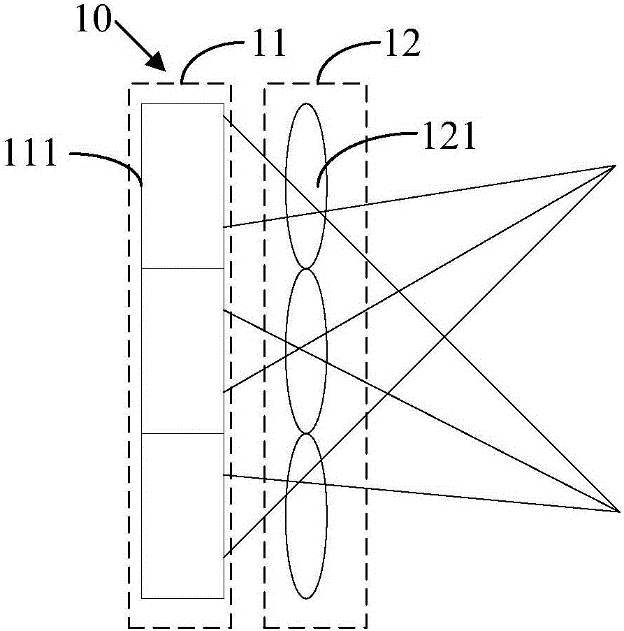
technical field [0001] The invention relates to the display field, in particular to a 3D display device. Background technique [0002] With the development of society, people have higher and higher requirements on the display quality of display panels, especially with the development of 3D display devices, users hope to have a 3D display device that is easy to operate and has low manufacturing cost. [0003] Such as figure 1 as shown, figure 1 It is a schematic structural diagram of an existing 3D display device. The 3D display device 10 includes a display unit 11 and a lens array 12 , the display unit 11 includes a plurality of sub-pixel units 111 ; the lens array 12 includes a plurality of lens units 121 . One lens unit 121 corresponds to at least one sub-pixel unit 111 . The display unit 11 projects orthogonally or perspectively into space through the lens array 12 to restore a 3D scene. Human eyes can see different images in a specific viewing area, thus forming a 3...

Claims


Application Information

Patent Timeline
IPC IPC(8): G02B27/22G02B30/27
CPCG02B30/26G02B30/27H04N13/305H04N13/31H04N13/324G02B5/201G02B5/28
Inventor 陈剑鸿
Owner TCL CHINA STAR OPTOELECTRONICS TECH CO LTD
Why Eureka
Try Eureka