Image display apparatus and image display method

Active Publication Date: 2011-09-29
SEIKO EPSON CORP
View PDF11 Cites 25 Cited by
  • Summary
  • Abstract
  • Description
  • Claims
  • Application Information

AI Technical Summary

Benefits of technology

[0023]According to the image display method of the aspect of the invention, the positions of the images of the pixels on the projection surface are temporally shifted if the images to be displayed are still images, and display resolution of the still images may be improved. On the other hand, the positions of the images of the pixels on t

Problems solved by technology

However, according to the method, it is necessary to increase the number of light modulation devices, and there is a problem that significant increase in costs is caused.
According to the method, it is unnecessary to increase the number of light modulation devices.
Therefore, the technology is suitable for still images having no temporal frequenc

Method used


Image

  • Image display apparatus and image display method
  • Image display apparatus and image display method
  • Image display apparatus and image display method

Examples


first embodiment

[0033]Hereinafter, the first embodiment of the invention will be explained using FIGS. 1 to 6.

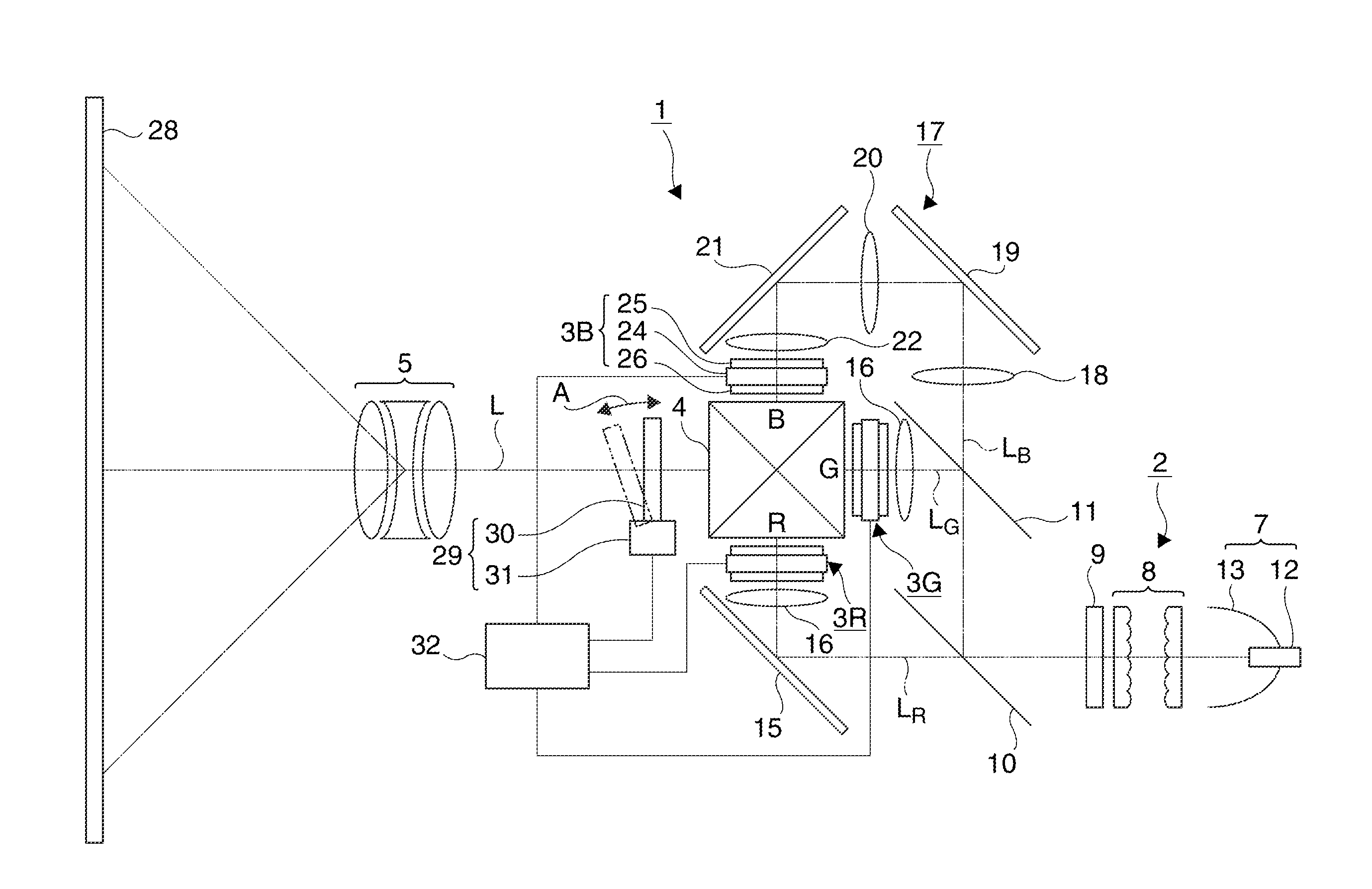
[0034]An image display apparatus of the embodiment is a configuration example of the so-called 3LCD projector having three liquid crystal light valves.

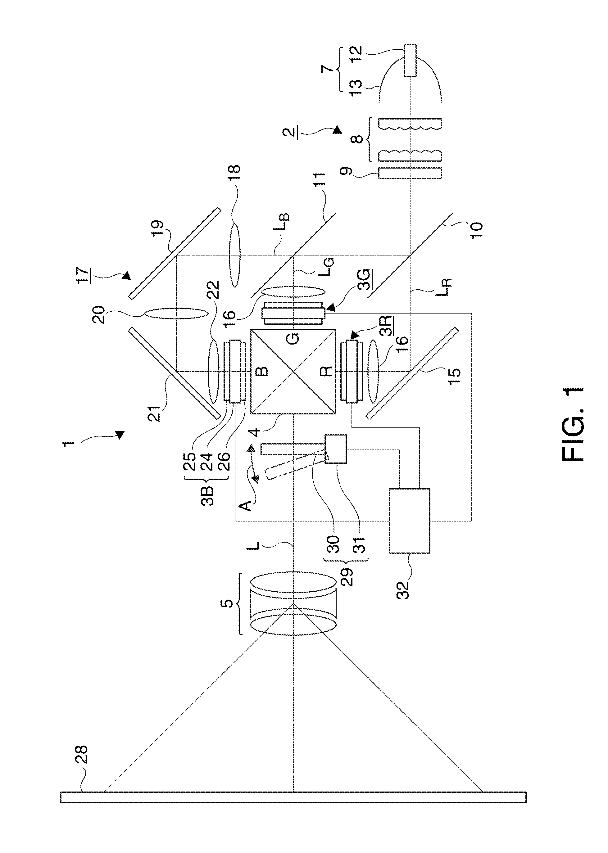
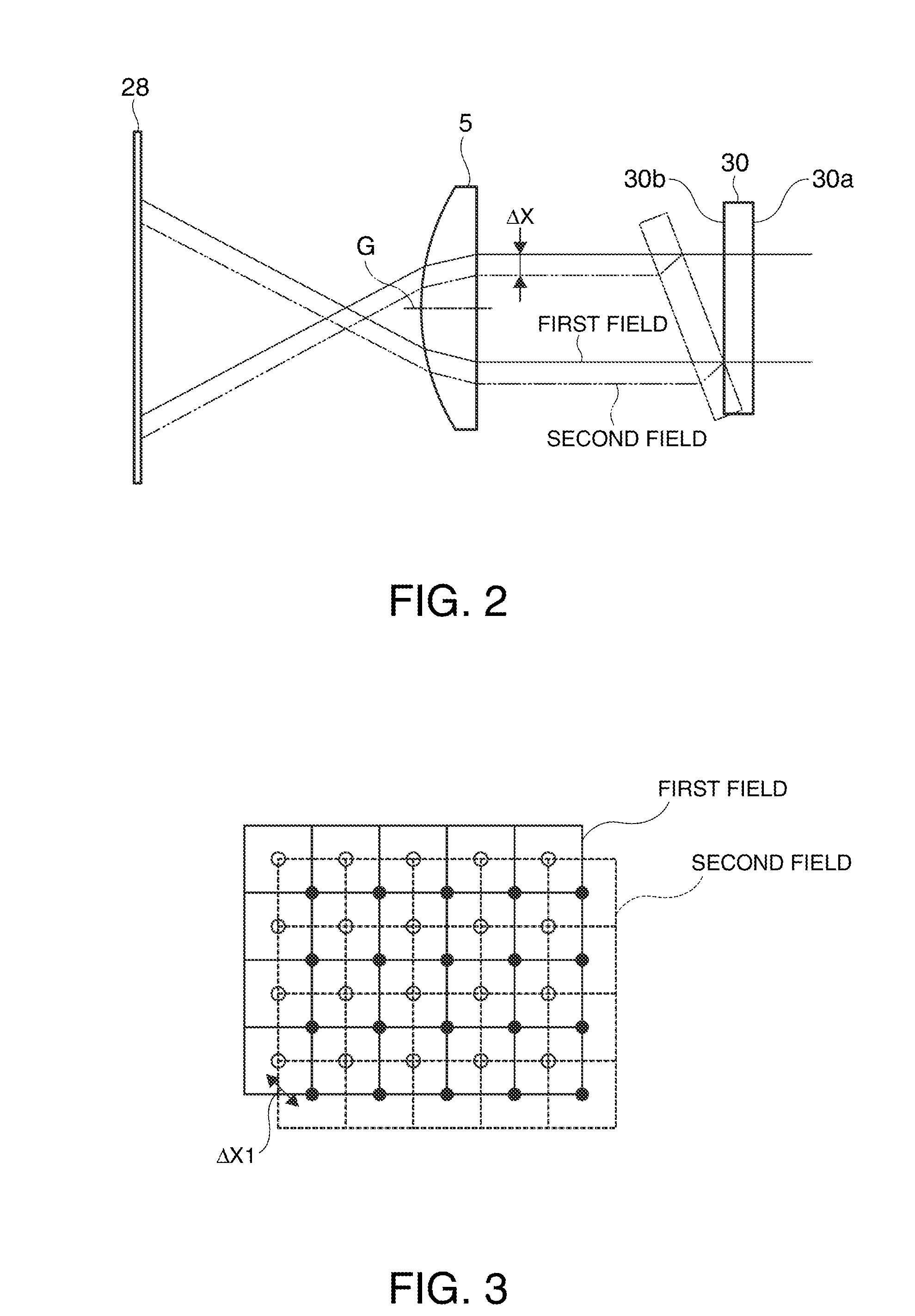
[0035]FIG. 1 is a schematic configuration diagram of the projector of the embodiment. FIG. 2 shows a state of optical axis shift when a light transmissive plate is driven. FIG. 3 is a conceptual diagram of shifted positions of pixel images. FIG. 4 is a block diagram showing a schematic configuration of a control unit. FIG. 5 is a block diagram showing a schematic configuration of a determination part within the control unit. FIG. 6 is a flowchart showing a flow of processing of the control unit.

[0036]Note that, in the respective following drawings, the ratios and scales of dimensions may be differed depending on component elements for facilitating visualization of the component elements.

[0037]The projector 1 (image display apparatus) of the e...

second embodiment

[0069]As below, the second embodiment of the embodiment will be explained using FIGS. 7 and 8.

[0070]An image display apparatus according to the invention is also a configuration example of the 3LCD projector and its basic configuration is the same as that of the first embodiment, and the explanation of the basic configuration of the projector will be omitted and only the configuration of the control unit will be explained.

[0071]FIG. 7 is a block diagram showing a configuration of a determination part within a control unit of the projector of the embodiment. FIG. 8 is a flowchart showing a flow of processing of the control unit.

[0072]The first embodiment has the configuration in which the control unit automatically determines the use or nonuse of the temporal axis pixel shift based on the difference computation of the image signals of the temporally adjacent two frames. On the other hand, the embodiment employs a configuration in which information for determination of use or nonuse o...


PUM


Abstract

An image display apparatus includes: a light source that outputs light; a light modulation device that has plural pixels arranged in a matrix and modulates the light from the light source; a projection system that projects the light modulated by the light modulation device onto a projection surface; a pixel image shift unit that can shift positions of images of the pixels of the light modulation device projected on the projection surface; and a control unit that controls the light modulation device and the pixel image shift unit, wherein the control unit can switch whether the pixel image shift unit temporally shifts the positions of the images of the pixels or not.

Description

[0001]This application claims priority to Japanese Patent Application No. 2010-070283, filed on Mar. 25, 2010, the entirety of which is hereby incorporated by reference.BACKGROUND[0002]1. Technical Field[0003]The present invention relates to an image display apparatus and an image display method.[0004]2. Related Art[0005]In a projection-type image display apparatus of such as a projector, in the case where the image display apparatus includes light modulation devices such as liquid crystal light valves, the resolution of an image projected on a screen is typically equal to the resolution of the light modulation devices (the number of horizontal pixels, the number of vertical pixels). In the following explanation, “resolution of image projected on screen” will be referred to as “display resolution”. Here, as a method of improving the display resolution without changing the resolution of the light modulation devices, there is a method of increasing the number of light modulation devic...

Claims


Application Information

Patent Timeline
IPC IPC(8): G09G5/10
CPCG09G3/003G09G2340/0407G09G5/399G09G3/005
Inventor WATANABE, RYOKI
Owner SEIKO EPSON CORP
Why Eureka
Try Eureka