Three-dimensional display device and three-dimensional display method thereof
A three-dimensional display and equipment technology, applied in optics, instruments, electrical components, etc., to achieve the effect of improving display resolution
- Summary
- Abstract
- Description
- Claims
- Application Information
AI Technical Summary
Problems solved by technology
Method used
Image
Examples
Embodiment 1
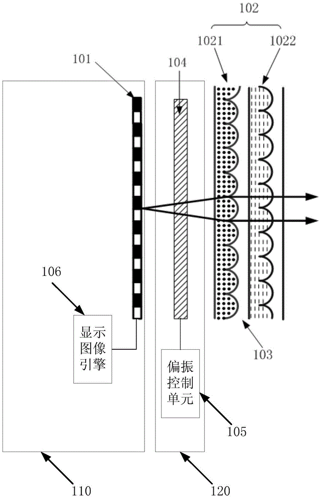
[0073] Such as Figure 3a , 3b As shown, the three-dimensional display device according to Embodiment 1 of the present invention includes: a display device 1110 , at least two layers of microlens arrays 1102 , and a polarizing device 1120 disposed between the display device and the microlens arrays.
[0074] Wherein, the display device 1110 specifically includes: a display screen 1101 and a display image engine 1106 .
[0075] The polarization device 1120 specifically includes: a polarization conversion device 104 and a polarization control unit 105 .
[0076] Further, the three-dimensional display device may further include: a spacer material layer 103 disposed between the microlens arrays 1102 of each layer.
[0077] Wherein, in the three-dimensional display device of Embodiment 1, each layer of microlens arrays 1102 is arranged parallel to the display screen 1101; the focal lengths of each layer of microlens arrays 1102 are the same, and the microlenses in each layer of m...
Embodiment 2
[0095] Such as Figure 4a , 4b As shown, the three-dimensional display device according to Embodiment 2 of the present invention includes: a display device 2110 , at least two layers of microlens arrays 1202 , and a polarizing device 2120 disposed between the display device and the microlens arrays.
[0096] Wherein, the display device 2110 specifically includes: a display screen 1201 and a display image engine 1206 .
[0097] The polarization device 2120 specifically includes: a polarization conversion device 104 and a polarization control unit 105 .
[0098] Further, the three-dimensional display device may further include: a spacer material layer 103 disposed between the microlens arrays 1202 of each layer.
[0099] Wherein, in the three-dimensional display device according to Embodiment 2 of the present invention, each layer of microlens arrays 1202 is arranged parallel to the display screen 1201; the focal lengths of each layer of microlens arrays 1202 are the same, and...
Embodiment 3
[0112] Such as Figure 5a , 5b As shown, the three-dimensional display device according to Embodiment 3 of the present invention includes: a display device 3110 , at least two layers of microlens arrays 1302 , and a polarizing device 3120 disposed between the display device and the microlens array.
[0113] Wherein, the display device 3110 specifically includes: a display screen 1301 and a display image engine 1306 .
[0114] The polarization device 3120 specifically includes: a polarization conversion device 104 and a polarization control unit 105 .
[0115] Further, the three-dimensional display device may further include: a spacer material layer 103 disposed between the microlens arrays 1302 of each layer.
[0116] The inventors of the present invention found that in the grating-type naked-eye three-dimensional display technology, the focal length of the lens determines the central depth plane, and the display depth range of the three-dimensional display is formed around ...
PUM
 Abstract
Description
Claims
Application Information
 - R&D
- Intellectual Property
- Life Sciences
- Materials
- Tech Scout
- Unparalleled Data Quality
- Higher Quality Content
- 60% Fewer Hallucinations
Browse by: Latest US Patents, China's latest patents, Technical Efficacy Thesaurus, Application Domain, Technology Topic, Popular Technical Reports.
© 2025 PatSnap. All rights reserved.Legal|Privacy policy|Modern Slavery Act Transparency Statement|Sitemap|About US| Contact US: help@patsnap.com


