Naked eye 3D (three-dimensional) television wall

A TV wall and 3D technology, applied in the direction of electrical components, optics, instruments, etc., to achieve the effect of high display resolution

Inactive Publication Date: 2011-11-09
SUISHEN TEC (BEIJING) CO LTD
View PDF6 Cites 26 Cited by
  • Summary
  • Abstract
  • Description
  • Claims
  • Application Information

AI Technical Summary

Problems solved by technology

Similarly, when a basic display unit on the LED display array is a group of three single-color red, green and blue LEDs, the way of interlacing and mixing of multi-view images and the design of the grating structure are no different from those used for liquid crystal panels.

Method used


Image

  • Naked eye 3D (three-dimensional) television wall
  • Naked eye 3D (three-dimensional) television wall
  • Naked eye 3D (three-dimensional) television wall

Examples


Embodiment 1

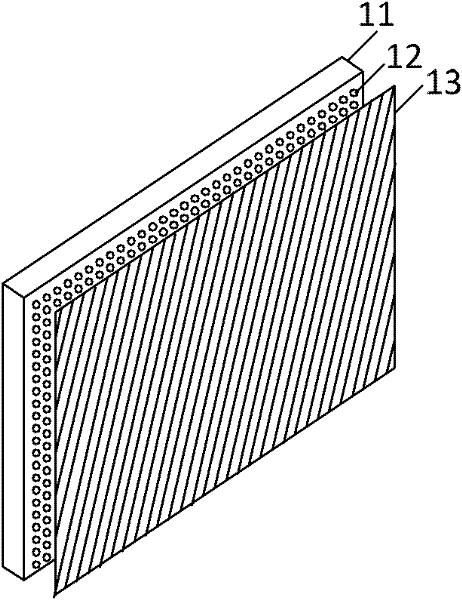
[0035] figure 1 It is a schematic diagram of the specific implementation of the naked-eye 3D TV wall realized by the full-color LED array. The naked-eye 3D video wall is composed of a full-color LED display array (11) and a slit grating (13) or a lenticular lens grating. The basic display unit of the LED array is a full-color LED tube (12). The slit grating or lenticular grating is placed in front of the LED array, parallel to the plane of the LED array, and at a certain angle to the column direction of the LEDs. If a 2D display resolution of 800×600 pixels is to be produced, 480,000 full-color LED tubes are required to be arranged on the display array. When the LED tube pitch is 4 mm, the area of ​​the whole LED array is about 3.2×2.4 square meters.

[0036]The basic unit of the full-color LED display array 11 is the full-color LED tube 12 . This LED tube 12 is actually formed by packaging three single-color LEDs of red, green and blue into one tube. This full-color LED ...

Embodiment 2

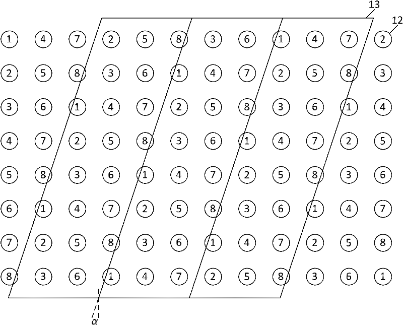
[0039] image 3 It is a schematic diagram of a grating structure design and a multi-view pixel interlaced mixing method in the case of 8 viewing angles; image 3 and figure 2 It is similar, but it shows a grating structure design and interlaced mixing method of multi-view images in the case of 8 viewing angles. As can be seen from the circle numbers of the LED tube (12), a new pixel interleaved mixing format is used here. In this case, the viewing angle K=8, M=3, N=8 / 3. That is, the horizontal resolution is reduced to 3 / 8 of the original, and the vertical resolution is reduced to 1 / 3 of the original. The interleaving and mixing method of multi-view views is as follows: adjacent pixels along the LED row direction come from a view with a viewing angle difference of M=3, and adjacent pixels along the LED column direction come from a view with a viewing angle difference of 1. When the LED tubes are arranged equidistantly in the horizontal and vertical directions, the column d...


PUM


Abstract

The invention relates to a naked eye 3D (three-dimensional) television wall, comprising a full-color LED (light-emitting diode) array and a slit grating (or a lenticular grating), wherein the grating is arranged in front of an LED display array and parallel to an array plane; and the grating and the row direction of LEDs form an angle of inclination. When multi-view images are displayed on the LED array in a staggered mixing way, huge 3D images can be observed on the LED television wall without special glasses. In the traditional naked eye 3D television wall, an LED group containing three monochrouic LEDs is used as a basic display unit, which is similar to a red green blue sub-pixel structure on an LCD (liquid crystal display) panel. On the contrast, in the naked eye 3D television wall disclosed by the invention, the full-color LEDs are taken as the basic display units, so that the display resolution higher than that of the monochrouic LEDs is provided under the same LED arrangement density. The staggered mixing way of the multi-view images and the grating structure design which are required in the manufacturing of the full-color LED based naked eye 3D television wall are described in the specification of the invention.

Description

technical field [0001] The invention relates to the field of stereoscopic display, in particular to a naked-eye 3D stereoscopic video wall realized by using a full-color light-emitting diode array. technical background [0002] In recent years, with the advancement of liquid crystal display technology, naked-eye 3D display technology, or autostereoscopic display technology, has made great progress. The principle of naked-eye 3D display technology is to send the images with subtle parallax on the display panel to the left and right eyes of the viewer through light occlusion or light refraction, etc., and fuse them in the brain to produce stereoscopic perception. At present, the main glasses-free 3D display technologies are mainly divided into two types: slit grating type and lenticular lens type. Since the grating is placed at an oblique angle to the column direction of the pixels, the loss of display resolution can be spread in both horizontal and vertical directions. For ...

Claims


Application Information

Patent Timeline
Patent Type & Authority Applications(China)
IPC IPC(8): H04N13/00G02B27/22G09F9/33G02B30/29G02B30/32
CPCH04N13/0422H04N13/0415H04N13/0404G02B27/2214H04N13/317H04N13/305H04N13/324G02B30/29G02B30/32G02B30/27
Inventor 杜杨洲姜太平
Owner SUISHEN TEC (BEIJING) CO LTD
Why Eureka
Try Eureka