Test device and method for researching friction characteristics between tire and actual pavement

A friction characteristic and test device technology, which is applied in the direction of automobile tire testing, measuring devices, and mechanical devices, can solve problems such as large energy consumption, increased equipment power, and difficult control of wheel slip rate, and achieves a smooth torque transmission process. , shorten the adjustment time, eliminate the effect of heating phenomenon

A friction characteristic and test device technology, which is applied in the direction of automobile tire testing, measuring devices, and mechanical devices, can solve problems such as large energy consumption, increased equipment power, and difficult control of wheel slip rate, and achieves a smooth torque transmission process. , shorten the adjustment time, eliminate the effect of heating phenomenon

CN109612929APending Publication Date: 2019-04-12西安凯德液压机电有限责任公司

Image

  • Test device and method for researching friction characteristics between tire and actual pavement
  • Test device and method for researching friction characteristics between tire and actual pavement
  • Test device and method for researching friction characteristics between tire and actual pavement

Examples


Embodiment 1

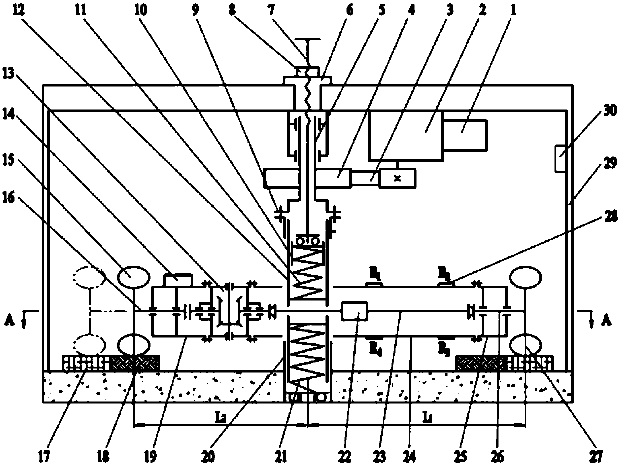
[0043] Such as figure 1 , figure 2 , the radius of the testing wheel 27 is equal to that of the auxiliary wheel 15, and the length L of the rotating arm of the testing wheel 27 1 Length L greater than the arm of the auxiliary wheel 15 2 , the transmission ratio of the power transmission box 13 is minus 1, that is, the rotational speeds of the two shaft ends of the power transmission box 13 are equal in magnitude and opposite in direction.

[0044] The motor 1 is equipped with a speed regulating device, the motor 1 is directly connected with the reducer 2, the reducer 2 is fixedly installed on the top of the frame 29, the output shaft of the reducer 2 is connected with the driven pulley 4 through the belt 3, and the driven pulley 4 It is fixedly connected with the central tube shaft 5; the central tube shaft 5 is hollow in the axial direction, and a loading screw 7 is arranged inside the central tube shaft 5, and the loading screw 7 is arranged on the axis of the central tub...

Embodiment 2

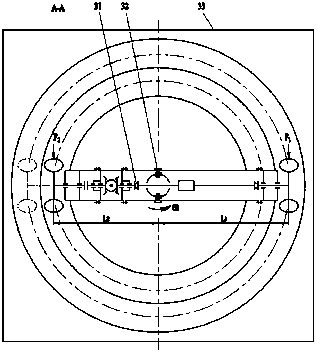
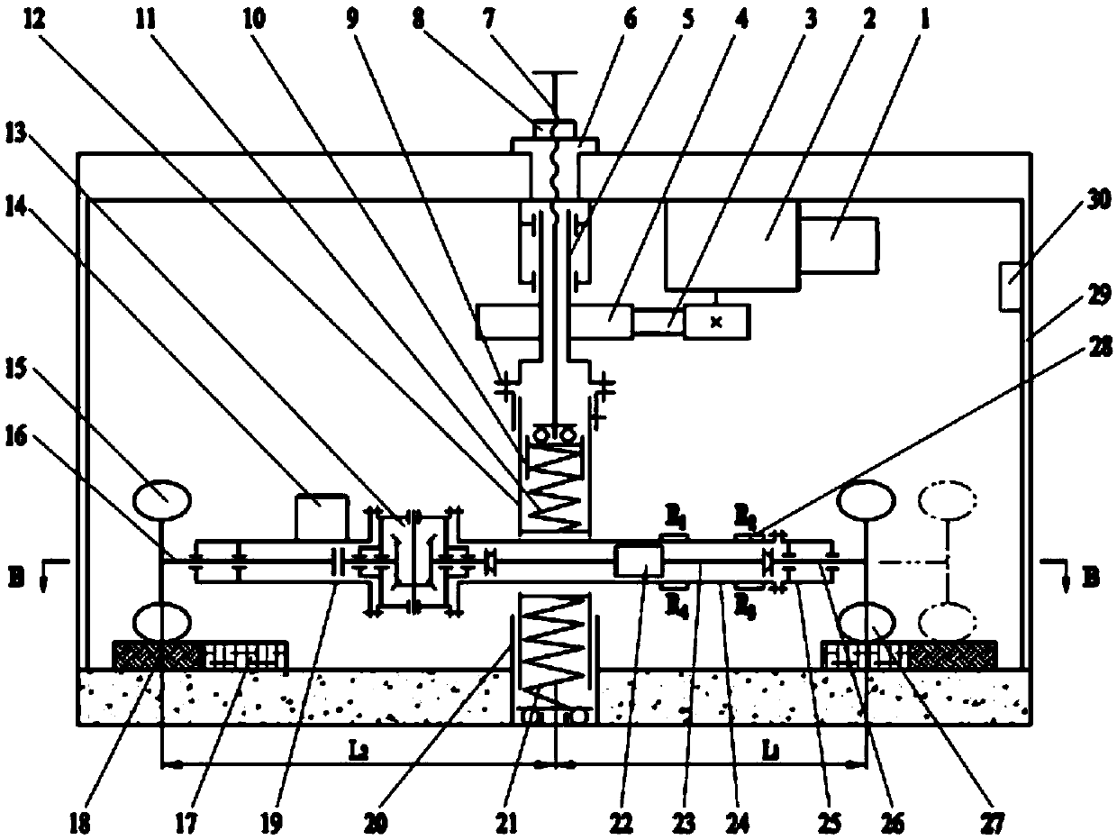
[0067] Such as image 3 , Figure 4As shown, in this embodiment, there is a large hole in the horizontal direction between the upper partition and the lower partition in the loading sleeve 12, and the rotating arm 24 passes through this large hole, and the rotating arm is driven by the driving pin 32. 24 is hinged with the loading sleeve 12, and the L 1 2 , the test loop 17 is arranged on the inside, and the auxiliary loop 18 is arranged on the outside. All the other structures are the same as in Example 1.

[0068] At this time, the auxiliary wheel 15 does not slip, but the running speed is fast, the actual speed of the test wheel 27 is slow, and it slips backward, and the slip rate σ is calculated according to the following formula:

[0069]

[0070] When the rotating arm 24 rotates at an angular velocity ω, the test wheel 27 slides backward, and the ground gives the test wheel 27 a forward friction force F 1 , friction force F 1 It is to drive the rotating arm 24 to...


PUM


Abstract

The invention discloses a test device and method for researching friction characteristics between a tire and an actual pavement, and belongs to the technical field of detecting equipment. Actual working conditions of the tire with load running on different pavements are well simulated through mechanical structures such as a loading sleeve, a loading sleeve base, a rotary arm and a rack, the test device and method for researching friction characteristics between the tire and the actual pavement can be used for testing a friction factor between the tire and the pavement and researching wear pattern between the tire and the pavement, compression amount of a loading spring can be adjusted through a loading screw according to requirements, and thus a test load is adjusted; meanwhile tire running speed is adjusted through a transmission system; changing is conducted on a slip rotary rate or a slip shift rate between the tire and a pavement through adjusting a connected relation between a tested wheel and an auxiliary wheel, multiple kinds of running conditions of the tire on the pavement are simulated, data such as the load, a rotate speed and a torque are detected in real time through asensor, and thus the friction factor between the tested tire and the tested pavement is obtained by formula calculation.

Description

technical field [0001] The invention belongs to the technical field of detection devices, and in particular relates to a test device and method for researching the friction characteristics of tires and actual road surfaces. Background technique [0002] At present, the number of various motor vehicles continues to increase, and the frequency of action of vehicle loads on the road surface is also increasing. The gravity of the vehicle load will deform the road surface and form ruts. When the vehicle starts, brakes, shifts, turns, and overcomes various resistances, it will exert a horizontal shear force on the road surface. This shear force will cause the road surface to move horizontally Under the above-mentioned complex alternating loads, the service life of the pavement is also greatly reduced. Specifically, on the one hand, the friction coefficient between the tire and the road will decrease with the wear and tear of the tire surface and the road surface, which will incre...

Claims


Application Information

Patent Timeline
12 Apr 2019
Publication
CN109612929A
IPC
G01N19/02; G01N3/56; G01M17/02
CPC
G01M17/02; G01N3/56; G01N19/02
Inventors
高彦军; 高军