Motor rotor heat sleeve rotating shaft cooling machine

A technology for motor rotors and coolers, applied in metal processing, metal processing equipment, manufacturing tools, etc., can solve problems such as affecting product quality, lack of heat-sleeve shafts for coolers, and unfavorable cooling uniformity.

Active Publication Date: 2019-04-16
鸡西德元电器有限公司
View PDF5 Cites 0 Cited by
  • Summary
  • Abstract
  • Description
  • Claims
  • Application Information

AI Technical Summary

Problems solved by technology

[0003] During cooling, the thermal sleeve shaft will have stress changes due to uneven cooling of the cooler, which will affect product quality. Some coolers lack a structure that can place and clamp the ther

Method used


Image

  • Motor rotor heat sleeve rotating shaft cooling machine
  • Motor rotor heat sleeve rotating shaft cooling machine
  • Motor rotor heat sleeve rotating shaft cooling machine

Examples


Example Embodiment

[0021] The technical solutions in the embodiments of the present invention will be clearly and completely described below in conjunction with the accompanying drawings in the embodiments of the present invention. Obviously, the described embodiments are only a part of the embodiments of the present invention, rather than all the embodiments. Based on the embodiments of the present invention, all other embodiments obtained by those of ordinary skill in the art without creative work shall fall within the protection scope of the present invention.
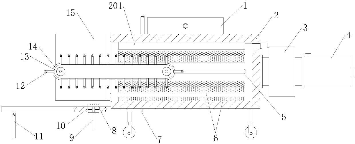
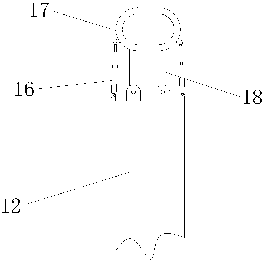
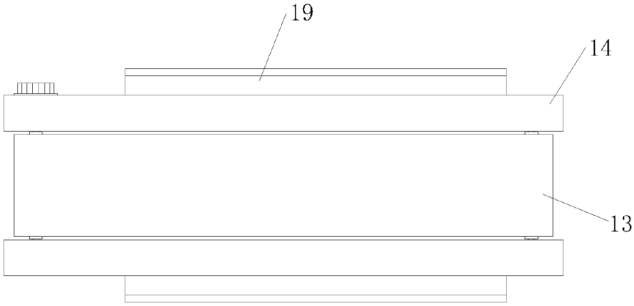
[0022] See Figure 1-4 As shown, a motor rotor thermal jacket shaft cooler includes a box frame 2, a suction fan 3, an iron tube 4, a cooling mechanism for cooling the motor rotor thermal jacket, and a motor rotor thermal jacket for fixing Push-and-place clamping mechanism, a suction fan 3 is installed in the middle of one side of the box frame 2, and an iron pipe 4 is installed at the outlet port of the suction fan 3, and activated carb...


PUM


Abstract

The invention belongs to the technical field of cooling machines, and particularly relates to a motor rotor heat sleeve rotating shaft cooling machine. The cooling machine comprises a compression refrigerator, a box body frame, a suction fan, an iron sheet tube, a strip-shaped sliding groove, strip-shaped grooves, a strip-shaped carrying plate, a square toothed plate, a pneumatic pushing rod, a rectangular groove, a supporting rod, support rods, a conveying belt, a strip-shaped side plate, a door plate, telescopic rods, semicircular clamping blocks, round rods and strip-shaped sliding blocks.The machine has the function of sequentially clamping and moving heat sleeve rotating shafts, the to-be-cooled heat sleeve rotating shafts can be rapidly placed in the cooling structure in a centralized mode, the cooling uniformity of the heat sleeve rotating shafts is facilitated, and the degree of stress changes, caused by non-uniform cooling, of the heat sleeve rotating shafts is reduced. A cold air cooling mode is used, high-temperature air enters an evaporation strip cover according to the principle that cold air descends and hot air rises, and an atomizing nozzle sprays mist-shaped liquid, so that the mist-shaped liquid is instantly vaporized and discharged through the suction fan as heat, and better heat dissipation and heat recycling are facilitated.

Description

technical field [0001] The invention belongs to the technical field of cooling machines, in particular to a motor rotor shrink-fit shaft cooling machine. Background technique [0002] The motor refers to an electromagnetic device that realizes the conversion or transmission of electric energy according to the law of electromagnetic induction. It is represented by the letter M in the circuit. Its main function is to generate driving torque as a power source for electrical appliances or various machinery. [0003] During cooling, the thermal sleeve shaft will have stress changes due to uneven cooling of the cooler, which will affect product quality. Some coolers lack a structure that can place and clamp the thermal sleeve shaft to be cooled in an orderly manner, and are generally in a cooling state. The thermal sleeve shaft will not move and the position is relatively fixed, which is not conducive to uniform cooling. In view of this, the present invention proposes a motor rot...

Claims


Application Information

Patent Timeline
IPC IPC(8): B23P11/02
CPCB23P11/025
Inventor 尹苑苑张辰星王金玉
Owner 鸡西德元电器有限公司
Why Eureka
Try Eureka