Micro large-speed-ratio speed reducer and needle gear positioning flange mounting method thereof

A technology for positioning flanges and reducers, which is applied to gear transmissions, mechanical equipment, transmissions, etc., and can solve the problems of small size of reducer and large transmission ratio of reducer

Inactive Publication Date: 2019-04-23
湖北斯微特传动有限公司
View PDF8 Cites 0 Cited by
  • Summary
  • Abstract
  • Description
  • Claims
  • Application Information

AI Technical Summary

Problems solved by technology

[0004] The main purpose of the present invention is to provide a miniature high-speed ratio reducer and its pin-tooth positioning flange installati...

Method used


Image

  • Micro large-speed-ratio speed reducer and needle gear positioning flange mounting method thereof
  • Micro large-speed-ratio speed reducer and needle gear positioning flange mounting method thereof
  • Micro large-speed-ratio speed reducer and needle gear positioning flange mounting method thereof

Examples


Embodiment 1

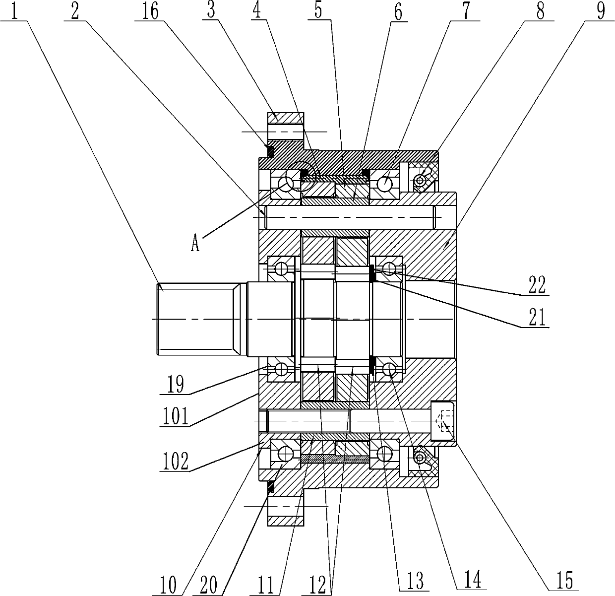
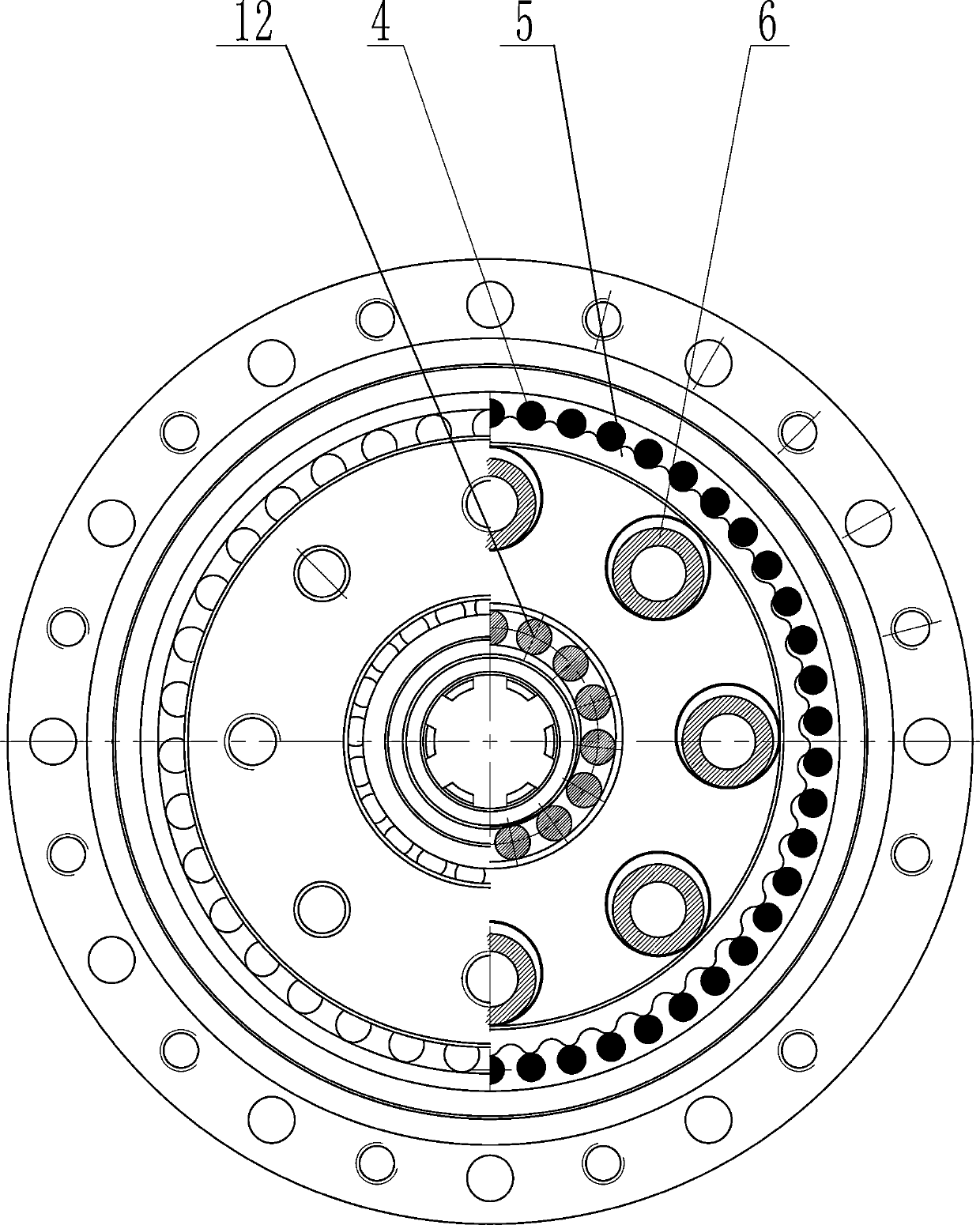
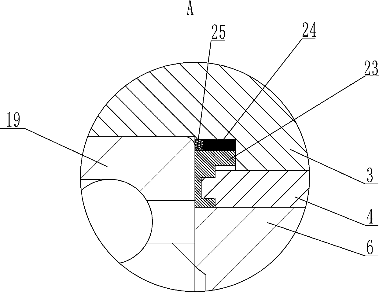
[0036] like Figure 1~9 As shown, a miniature high-speed ratio reducer includes a casing 3, an output seat 9 and an input shaft 1. The input shaft 1 is fixed with two eccentric wheels with a phase difference of 180°, and the two eccentric wheels pass through the crank bearing 12 respectively. Connected with a cycloidal wheel 5, a plurality of needle-toothed pins 4 are arranged along the circumference on the inner wall of the casing 3, and the needle-toothed pins 4 are intermittently meshed with two cycloidal wheels 5, and the inside of the casing 3 is provided with a needle-toothed positioning flange 23, A plurality of pin tooth pin positioning holes 232 are provided on the surface of the inner ring of the pin tooth positioning flange 23, the pin tooth positioning flange 23 is located at both ends of the pin tooth pin 4, and the two ends of the pin tooth pin 4 are provided with positioning cylinders 41 , the positioning cylinder 41 is placed in the pin tooth pin positioning ho...

Embodiment 2

[0048] A miniature high-speed-ratio reducer and its pin-tooth positioning flange installation method, the method comprising:

[0049] 1) After finishing the pin tooth positioning flange 23, knurling is performed on its surface, and knurling is processed after finishing. The knurling plays a better role in stability in the interference fit, and also prevents the flat surface from collapsing after the fit. loose phenomenon;

[0050] 2) Install one of the needle-tooth positioning flanges 23, install the positioning pin 24 on the positioning groove 31 inside the housing 3, and align the flange positioning groove 231 of the needle-tooth positioning flange 23 with the positioning pin 24 on the positioning groove 31. Cooperate to position the pin-tooth positioning flange 23, which plays the role of positioning and also plays the role of anti-rotation;

[0051] 3) After positioning, cold fit the pin tooth positioning flange 23. After the installation is completed, install the pin too...


PUM

PropertyMeasurementUnit
Outer diameteraaaaaaaaaa
Thicknessaaaaaaaaaa

Abstract

The invention discloses a micro large-speed-ratio speed reducer. The micro large-speed-ratio speed reducer comprises a housing, an output base and an input shaft, wherein eccentric wheels are fixedlyarranged on the input shaft; the two eccentric wheels are separately connected to cycloidal gears through crank bearings; a plurality of pin gear pins are arranged at the periphery of the inner wall of the housing; the pin needle gears are in intermittent engagement with two cycloidal gears; the outer diameter of the housing of the speed reducer is not greater than 45 mm; and the thickness of thespeed reducer is not smaller than 26.4 mm. The speed reducer is smaller in size, and operation of a mounting mechanical hand is more flexible, so that use, in the field with insufficient output torqueof a harmonic speed reducer, can be completely replaced.

Description

[0001] A miniature high-speed ratio reducer and its pin tooth positioning flange installation method. technical field [0002] The invention relates to a reducer, in particular to a miniature high-speed ratio reducer and a method for installing the pin-tooth positioning flange thereof. Background technique [0003] The reducer is a device widely used in various mechanical equipment, and the design of the reducer directly affects the transmission performance of the mechanical equipment. At present, the widely used cycloidal pinwheel reducer has the advantages of high transmission efficiency and large speed ratio. With the rapid development of today's robotic arms, the use of micro-mechanical arms has also been valued, but the reducer inside the general robotic arm requires The transmission ratio is large, but the general shape of the reducer with large transmission ratio is relatively large, and the general miniature reducer cannot meet the requirements. Secondly, the general...

Claims


Application Information

Patent Timeline
IPC IPC(8): F16H1/32F16H57/023
CPCF16H1/32F16H57/023
Inventor 董红刚余运清程志毅
Owner 湖北斯微特传动有限公司
Why Eureka
Try Eureka