Underground diaphragm wall with anti-seepage joints and construction method of underground diaphragm wall

A technology for underground diaphragm walls and joints, applied in artificial islands, sheet pile walls, water conservancy projects, etc., can solve the problems of punching shear damage, insufficient joint stiffness, long welds, etc., and achieve the effect of enhancing stiffness

Pending Publication Date: 2019-05-14
HEFEI UNIV OF TECH +1
View PDF0 Cites 12 Cited by
  • Summary
  • Abstract
  • Description
  • Claims
  • Application Information

AI Technical Summary

Problems solved by technology

However, there are also some problems in the I-steel joints, mainly including the welding between the I-steel joint and the steel cage, the weld seam is long, and there is insufficient welding strength to cause joint deformation; the I-steel joint is only composed of an I-steel plate and a water-stop Composed of steel plates, the joint itself is not rigid enough, which can easily lead to punching shear damage

Method used


Image

  • Underground diaphragm wall with anti-seepage joints and construction method of underground diaphragm wall
  • Underground diaphragm wall with anti-seepage joints and construction method of underground diaphragm wall
  • Underground diaphragm wall with anti-seepage joints and construction method of underground diaphragm wall

Examples


Embodiment 1

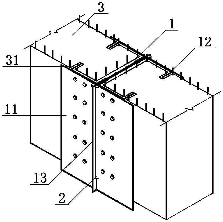
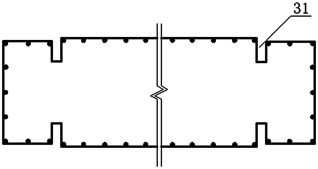
[0035] An underground continuous wall with anti-seepage joints, including a wall structure formed by pouring concrete from a steel cage 3, and an anti-seepage joint 1 connecting the adjacent wall structures;

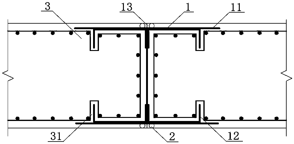
[0036] The anti-seepage joint 1 includes I-shaped steel 11, the I-shaped steel 11 is vertically arranged in the groove, the I-shaped steel web 112 is located at the joint of the adjacent reinforcement cage 3, and the I-shaped steel flanges on both sides The horizontal direction of 111 is consistent with the horizontal extension direction of the wall structure, and the vertical direction is consistent with the longitudinal extension direction of the wall structure;

[0037] The outer sides of the I-steel flanges 111 on both sides correspond to the I-steel webs 112 and are respectively provided with waterproof steel plates 13, and each water-sealed steel plate 13 is perpendicular to the I-steel flanges 111, and the arrangement direction is the same as that of the I-steel we...

Embodiment 2

[0041] A construction method for an underground diaphragm wall with anti-seepage joints, comprising the following steps:

[0042] (1) The trench for the underground diaphragm wall shall be dug in advance, and the side wall and bottom of the trench shall be as smooth and clean as possible.

[0043](2) Connect the I-beam 11 and the channel steel 12 together by bolts, and then weld the water-stop steel plate 13 on the outside of the I-beam flange 111 on both sides corresponding to the I-beam web 112, and the I-beam 11. The channel steel 12 and the waterproof steel plate 13 constitute the anti-seepage joint 1 .

[0044] (3) Hang the anti-seepage joint 1 vertically in the trench. The depth of the bottom of the anti-seepage joint 1 inserted into the soil layer is 30cm. The trench is divided into two sections on the left and right. The two slot sections of the are completely separated;

[0045] The grouting pipes 2 are respectively arranged on both sides of the water-stop steel pla...


PUM


Abstract

The invention relates to the technical field of engineering construction, in particular to an underground diaphragm wall with anti-seepage joints and a construction method of the underground diaphragmwall. The underground diaphragm wall comprising wall body structure continuously arranged and the anti-seepage joints connected with adjacent wall body structures, and the wall body structures are formed by pouring concrete into reinforcement cages. Each anti-seepage joint comprises I-shaped steel, a water stop steel plate and channel steel, the channel steel is located on opposite sides of two I-shaped steel flanges and corresponds to two sides of an I-shaped steel web, and a bottom groove plate of each channel steel is fixedly connected with the corresponding I-shaped steel flange. Groovesare formed in steel channel legs, corresponding to one side of each steel channel, of each reinforcement cage, and each groove is in clearance fit with the corresponding steel channel leg. The I-shaped steel and the four steel channels are connected through bolts to serve as main stress components of the anti-seepage joints, meanwhile, the steel channel legs on one of sides of the steel channels are in clearance fit with the grooves in the corresponding steel reinforcement cages, the steel reinforcement cages are fixed, and therefore the overall rigidity of the underground diaphragm wall is large, and the anti-seepage effect is good.

Description

technical field [0001] The invention relates to the technical field of engineering construction, in particular to an underground continuous wall with anti-seepage joints and a construction method thereof. Background technique [0002] The overall rigidity of the underground diaphragm wall is high, and the anti-seepage effect is good. Therefore, it is often used as a permanent underground building structure for retaining soil, seepage prevention and load bearing in engineering. Due to the long longitudinal length of the underground diaphragm wall, it needs to be divided into multiple groove sections during construction, and the groove sections are connected by joints, so the quality of the joints often affects the construction speed and the quality of the underground diaphragm wall, and the lighter ones cause the underground diaphragm wall to be discontinuous , In severe cases, the joints will leak water, which will cause uneven stress on the underground diaphragm wall, resu...

Claims


Application Information

Patent Timeline
Patent Type & Authority Applications(China)
IPC IPC(8): E02D5/20E02D29/16E02D31/02E02D15/02
Inventor 汪亦显刘飞飞盛明宏常乃坤李娴吕卫柯
Owner HEFEI UNIV OF TECH
Why Eureka
Try Eureka