

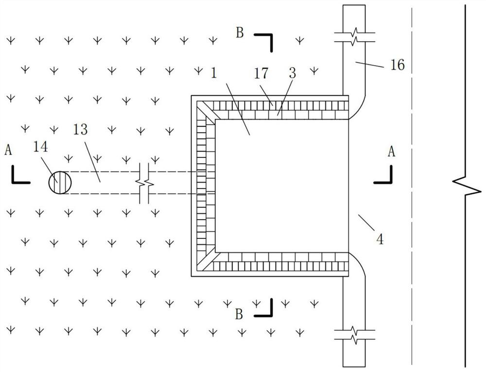
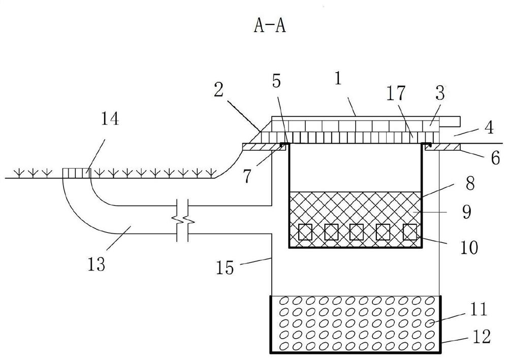
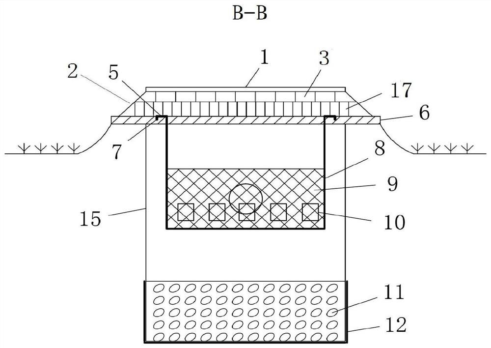
Inlet structure of a bioretention facility
A bioretention and inflow technology, which is applied to drainage structures, grease/oily substance/floating matter removal devices, chemical instruments and methods, etc., can solve the problems of debris filtration, plant damage at the entrance, etc., and reduce the inflow velocity , reduce maintenance costs, and ensure the effect of overcurrent capacity
- Summary
- Abstract
- Description
- Claims
- Application Information
AI Technical Summary
Problems solved by technology
Method used
Image

Examples
Embodiment Construction
[0028] The specific implementation manners of the present invention will be further described in detail below in conjunction with the accompanying drawings and embodiments. The following examples are used to illustrate the present invention, but are not intended to limit the scope of the present invention.
[0029] In the description of the present invention, it should be noted that unless otherwise specified and limited, the terms "installation", "connection" and "connection" should be understood in a broad sense, for example, it can be a fixed connection or a detachable connection. Connected, or integrally connected; it may be mechanically connected or electrically connected; it may be directly connected or indirectly connected through an intermediary, and it may be the internal communication of two components. Those of ordinary skill in the art can understand the specific meanings of the above terms in the present invention in specific situations.
[0030] refer to Figur...
PUM
 Abstract
Description
Claims
Application Information