
Inflow port structure for biological retention facility

A bioretention and inflow technology, which is applied in drainage structures, grease/oily substance/floating matter removal devices, water/sludge/sewage treatment, etc., can solve the problems of inability to damage plants at the entrance and filter debris, and achieve The effect of reducing maintenance costs, reducing inflow velocity, and reducing hazards

Active Publication Date: 2019-05-17
BEIJING UNIVERSITY OF CIVIL ENGINEERING AND ARCHITECTURE
View PDF10 Cites 2 Cited by
  • Summary
  • Abstract
  • Description
  • Claims
  • Application Information

AI Technical Summary

Problems solved by technology

[0006] The purpose of the present invention is to provide a bioretention facility inflow structure to solve the problems that the existing bioretention facility inflow easily causes damage to the plants at the entrance and cannot filter the debris in the rainwater runoff during heavy rainfall

Method used


Image

  • Inflow port structure for biological retention facility
  • Inflow port structure for biological retention facility
  • Inflow port structure for biological retention facility

Examples


Embodiment Construction

[0028] The specific implementation manners of the present invention will be further described in detail below in conjunction with the accompanying drawings and embodiments. The following examples are used to illustrate the present invention, but are not intended to limit the scope of the present invention.

[0029] In the description of the present invention, it should be noted that unless otherwise specified and limited, the terms "installation", "connection" and "connection" should be understood in a broad sense, for example, it can be a fixed connection or a detachable connection. Connected, or integrally connected; it can be mechanically connected or electrically connected; it can be directly connected or indirectly connected through an intermediary, and it can be the internal communication of two components. Those of ordinary skill in the art can understand the specific meanings of the above terms in the present invention in specific situations.

[0030] refer to Figur...


PUM

PropertyMeasurementUnit
Angleaaaaaaaaaa

Abstract

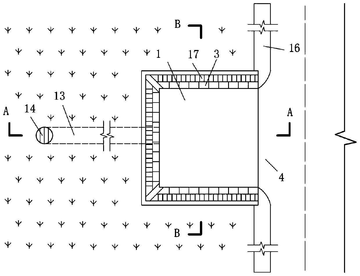
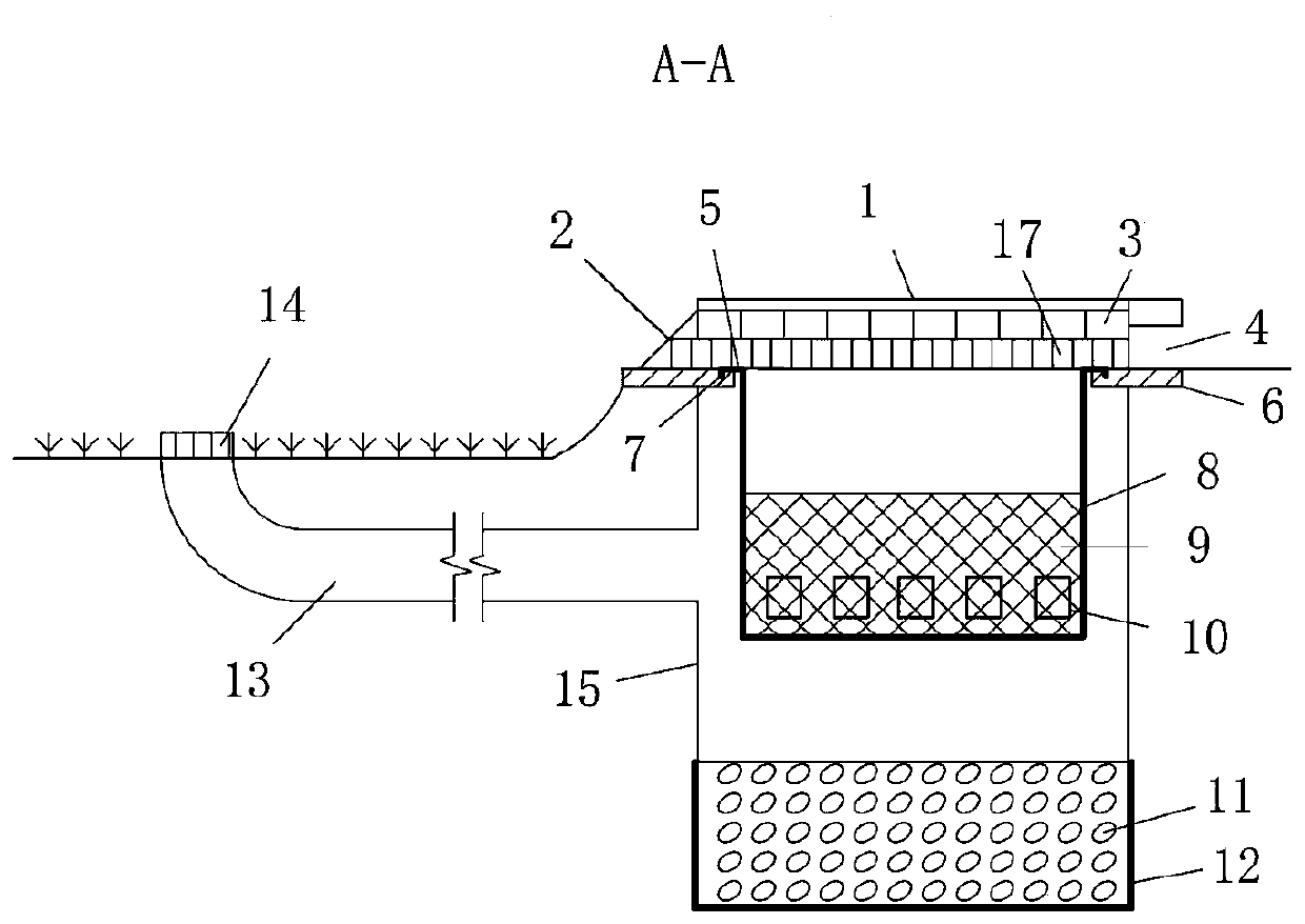
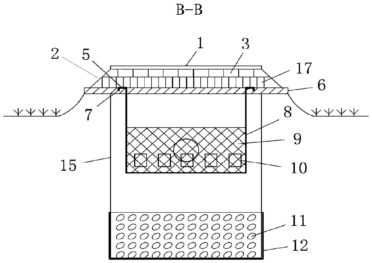
The invention provides an inflow port structure for a biological retention facility, which comprises a top cover, an overflow grille and a barrel of which the top is open. The overflow grille is arranged along the circumferential direction of the top end of the barrel; the top end of the barrel is in parallel and level to the side edge of a road; an inflow port is formed at one side of the overflow grille, which is close to the road; a filtering device is arranged inwards at the position of an opening of the barrel; the side wall of the barrel is connected with a water outlet pipe; and a wateroutlet of the water outlet pipe is lower than the plane where the top end of the barrel is positioned. According to the inflow port structure for the biological retention facility, which is providedby the invention, by arranging the filtering device and the overflow grille, in a case of light rain, after sundries in rainfall runoff are filtered by the filtering device, when the sundries are accumulated to a certain amount, the sundries directly flow into the biological retention facility through the water outlet of the water outlet pipe; and in a case of heavy rain, the sundries directly overflow into the biological retention facility through the overflow grille, so as to implement low-flow water outlet pipe inflow and high-flow overflow dispersed inflow modes, reduce scouring on plantsnear an inflow port and ensure excellent operation of the biological retention facility.

Description

technical field [0001] The invention relates to the technical field of rainwater collection and purification in a sponge city, and more particularly relates to an inflow structure of a biological retention facility. Background technique [0002] Urban runoff pollution seriously threatens the safety of urban water environment. Due to the large amount of exhaust gas, hydrocarbons and particulate matter produced by the burning of fossil energy by motor vehicles on the road, the oil substances that are not fully burned and leaked during the operation of vehicles, as well as tire wear and brakes are formed. Tire particulate matter and heavy metal substances, etc., cause road rainwater runoff pollution to be particularly serious. In order to deal with road rainwater runoff pollution, under the concept of sponge city construction, bioretention facilities provide an effective way to solve road rainwater runoff pollution. However, due to the serious pollution of road runoff, it dire...

Claims


Application Information

Patent Timeline
IPC IPC(8): E03F5/04E03F5/046E03F5/06E03F5/14
Inventor 张伟付子真孙慧超车伍李俊奇
Owner BEIJING UNIVERSITY OF CIVIL ENGINEERING AND ARCHITECTURE
Learn More