electrical connector

An electrical connector and abutting part technology, which is applied in the direction of connection and connection device components, circuits, etc., can solve the problems of increasing the material of the grounding terminal, increasing the width of the grounding terminal, and increasing the space occupied by the grounding terminal, so as to reduce the occupation of the grounding terminal. space, reduce impedance, and improve performance

Active Publication Date: 2020-08-28
DEYI PRECISION ELECTRONIC IND CO LTD PANYU
View PDF8 Cites 0 Cited by
  • Summary
  • Abstract
  • Description
  • Claims
  • Application Information

AI Technical Summary

Problems solved by technology

Since the crimping arm of the ground terminal abuts against the upper shielding piece, the crosstalk of the signal terminal can be shielded; however, since the crimping arm is arranged on the second elastic arm of the ground terminal side, so that the setting of the crimping arm increases the width of the ground terminal, resulting in an increase in the space occupied by the ground terminal and an increase in the material of the ground terminal, thereby increasing the production cost of the ground terminal, and in the insulation More grounding terminals and signal terminals cannot be arranged in the limited space of the body, which is not conducive to the transmission of more signals by the shielded connector, and thus is not conducive to improving the performance of the electrical connector

Method used


Image

  • electrical connector
  • electrical connector
  • electrical connector

Examples


Embodiment Construction

[0034] In order to facilitate a better understanding of the purpose, structure, features, and effects of the present invention, the present invention will now be further described in conjunction with the accompanying drawings and specific embodiments.

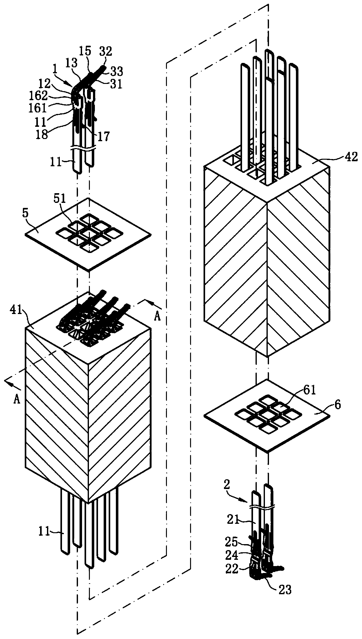
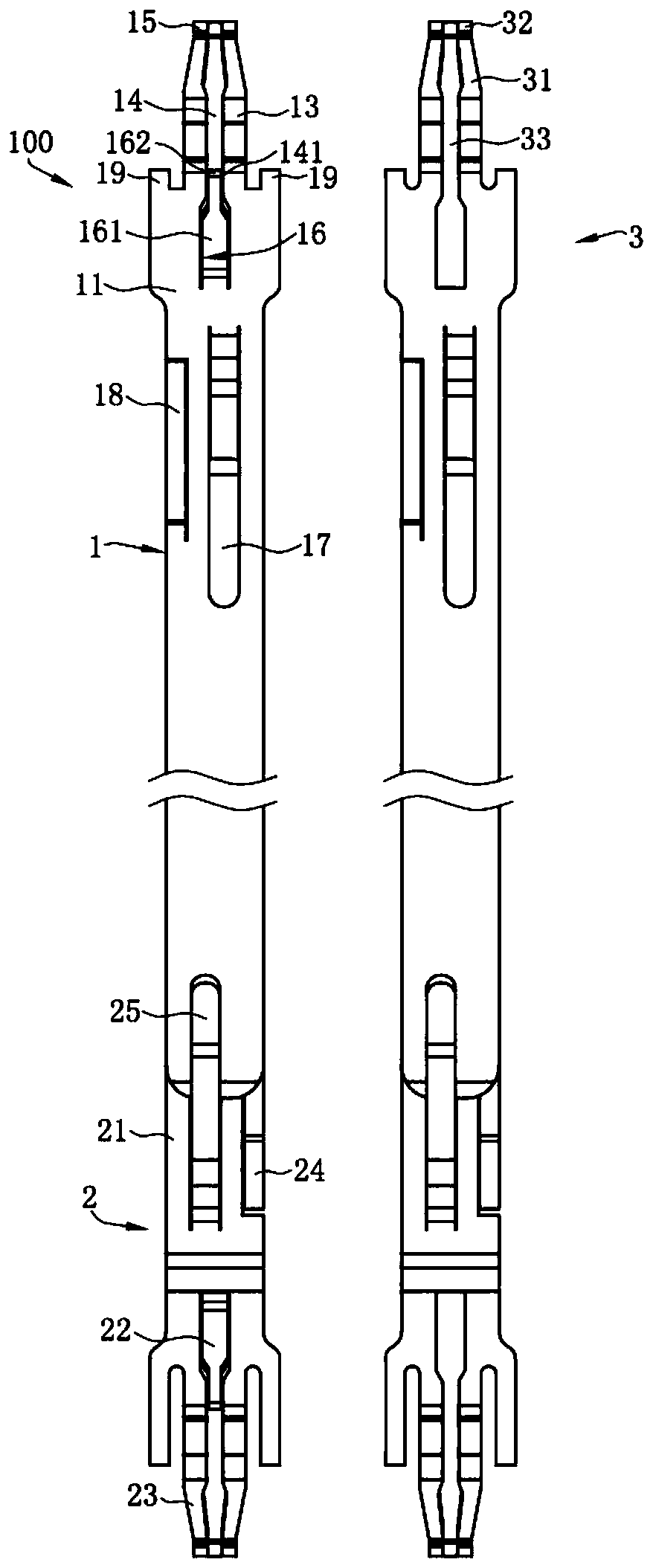
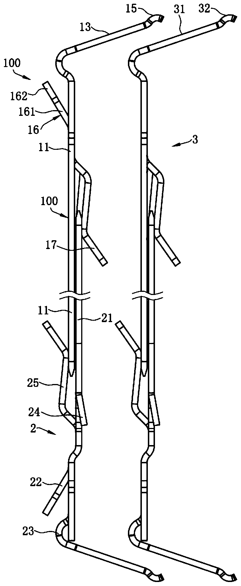
[0035] Such as Figure 1 to Figure 14 Shown is an embodiment of the electrical connector of the present invention, the electrical connector is used to electrically connect a chip module 200 to a circuit board 300, which includes: an insulating body 4; a plurality of housings accommodated in the insulating body 4 A ground terminal 100 and a plurality of signal terminals 3, the ground terminal 100 and the signal terminals 3 abut against the chip module 200 upwards, and connect to the circuit board 300 downwards; a shielding sheet 5 covers the insulating body 4 The upper surface and a metal sheet 6 cover the lower surface of the insulating body 4 , and the ground terminal 100 is connected to the shielding sheet 5 and the metal she...


PUM


Abstract

The invention provides an electric connector, comprising: an insulating main body; a shielding piece disposed on the insulating main body; at least one grounding terminal located in the insulating main body, wherein the grounding terminal has a base portion, a first elastic arm is formed by bending and extending upward from the base portion, the first elastic arm is provided with a through groove,the left and right sides of the through groove have two inner side edges, a first contact portion is formed by extending backward from the first elastic arm, an abutting portion is formed by bendingand extending upward from the base portion to abut against the shielding piece, the abutting portion has a free portion, the width of the free portion is less than or equal to the distance between thetwo inner side edges, and the free portion is formed between the two inner side edges; and a plurality of signal terminals located in the insulating main body. The electric connector can shield the crosstalk of the signal terminals and can also reduce the space occupied by the grounding terminal.

Description

【Technical field】 [0001] The invention relates to an electrical connector, in particular to a shielded electrical connector. 【Background technique】 [0002] A shielded connector for electrically connecting a chip module to a circuit board, comprising: an insulating body, and a plurality of signal terminals and a plurality of grounding terminals accommodated in the insulating body, each of the signal terminals has a The first base is bent upward from the top end of the first base to form a first elastic arm, and extends vertically downward from the first base to form a first tail; each of the ground terminals has a second The base is bent and extended upwards from the top of the second base to form a second elastic arm and a crimping arm, the crimping arm is located on one side of the second elastic arm, extending vertically from the second base The lower part is extended to form a second tail portion; an upper shielding sheet, the upper shielding sheet covers the upper surf...

Claims


Application Information

Patent Timeline
Patent Type & Authority Patents(China)
IPC IPC(8): H01R12/70H01R13/04H01R13/24H01R13/646H01R13/6591
Inventor 彭治国
Owner DEYI PRECISION ELECTRONIC IND CO LTD PANYU
Why Eureka
Try Eureka