Method and device, storage medium and processor for determining working mode of conveying line

A working mode and conveyor line technology, applied in the direction of conveyor control devices, transportation and packaging, conveyor objects, etc., can solve problems such as complicated, inefficient, and unproposed solutions, and achieve low flexibility and high flexibility sexual effect

Active Publication Date: 2021-10-08
ZHUHAI GREE INTELLIGENT EQUIP CO LTD +1
View PDF9 Cites 0 Cited by
  • Summary
  • Abstract
  • Description
  • Claims
  • Application Information

AI Technical Summary

Problems solved by technology

At present, there is a contradiction between the high-efficiency and fast requirements of the automated production line and the inefficient and complicated material distribution, which affects the entire production process to a certain extent.
[0003] In view of the low flexibility of the material buffer conveyor line in the above-mentioned related technologies, no effective solution has been proposed so far

Method used


Image

  • Method and device, storage medium and processor for determining working mode of conveying line
  • Method and device, storage medium and processor for determining working mode of conveying line
  • Method and device, storage medium and processor for determining working mode of conveying line

Examples


Embodiment 1

[0044] According to an embodiment of the present invention, a method embodiment of a method for determining the working mode of a conveying line is provided. It should be noted that the steps shown in the flow chart of the accompanying drawings can be implemented in a computer system such as a set of computer-executable instructions and, although a logical order is shown in the flowcharts, in some cases the steps shown or described may be performed in an order different from that shown or described herein.

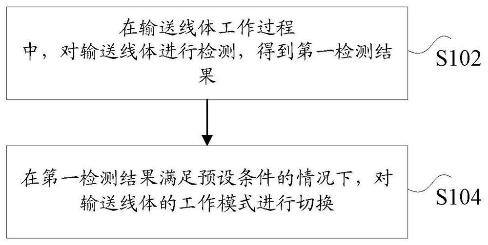
[0045] figure 1 is a flow chart of a method for determining the working mode of a conveying line according to an embodiment of the present invention, such as figure 1 As shown, the method for determining the working mode of the conveyor line includes the following steps:

[0046] In step S102, during the working process of the conveying line, the conveying line is detected to obtain a first detection result.

[0047] Specifically, the above-mentioned conveying line body ...

Embodiment 2

[0077] According to another aspect of the embodiment of the present invention, a device for determining the working mode of the transmission line is also provided, Image 6 is a schematic diagram of a device for determining the working mode of a conveying line according to an embodiment of the present invention, such as Image 6 As shown, the device for determining the working mode of the conveyor line includes:

[0078] The detecting unit 61 is configured to detect the conveying line body during the working process of the conveying line body, and obtain a first detection result.

[0079] The switching unit 63 is configured to switch the working mode of the transmission line body when the first detection result meets the preset condition, wherein the working mode includes: buffer mode and priority mode, and the buffer mode is used to indicate that the transmission line body The materials on the conveying line are cached, and the priority mode is used to indicate the conveying...

Embodiment 3

[0094] According to another aspect of the embodiments of the present invention, a storage medium is also provided, and the storage medium includes a stored program, wherein the program executes the method for determining the working mode of the transmission line in any one of the first embodiment.


PUM


Abstract

The invention discloses a method and device for determining the working mode of a conveying line, a storage medium and a processor. Wherein, the method includes: during the working process of the conveying line body, detecting the conveying line body to obtain the first detection result; when the first detection result satisfies the preset condition, switching the working mode of the conveying line body, Wherein, the working mode includes: a buffer mode and a priority mode, the buffer mode is used to instruct to buffer the materials on the conveying line body, and the priority mode is used to instruct to convey the materials on the conveying line body. The invention solves the technical problem of low flexibility of the material buffer conveying line in the related art.

Description

technical field [0001] The present invention relates to the technical field of production automation, in particular to a method and device for determining the working mode of a conveying line, a storage medium, and a processor. Background technique [0002] With the development of the market economy, production enterprises have put forward higher requirements for production diversification and high efficiency. The automation industry is facing huge challenges, and the requirements for automated production lines are also increasing. At present, there is a contradiction between the high-efficiency and fast requirements of the automated production line and the inefficient and complicated material distribution, which affects the entire production to a certain extent. [0003] Aiming at the problem of low flexibility of the material buffer conveying line in the above-mentioned related art, no effective solution has been proposed so far. Contents of the invention [0004] Embod...

Claims


Application Information

Patent Timeline
Patent Type & Authority Patents(China)
IPC IPC(8): B65G43/00B65G43/08
Inventor 张海锋卢强张凡英李德权
Owner ZHUHAI GREE INTELLIGENT EQUIP CO LTD
Why Eureka
Try Eureka