Anorectal patch composite forming machine

A molding machine, anorectal technology, applied in the direction of dressings, viscous dressings, etc., can solve the problems of low production efficiency, mutual misalignment, poor molding effect, etc., to achieve the effect of improving production efficiency, avoiding misalignment, and improving molding effect

Active Publication Date: 2019-06-25
四川艾医生医疗科技有限公司
View PDF11 Cites 1 Cited by
  • Summary
  • Abstract
  • Description
  • Claims
  • Application Information

AI Technical Summary

Problems solved by technology

[0004] Aiming at the defects of low production efficiency, poor molding effect and misalignment between product layers in the prior art, the present invention discloses an anorectal application. The application of the present invention can not only greatly improve the production efficiency of the application, but also apply various The layers fit well, avoiding misalignment between the layers, and at the same time improving the shaping effect, ensuring the perfect fit between the application and the human body, and improving the treatment effect

Method used


Image

  • Anorectal patch composite forming machine
  • Anorectal patch composite forming machine
  • Anorectal patch composite forming machine

Examples


Embodiment 1

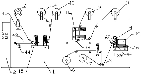
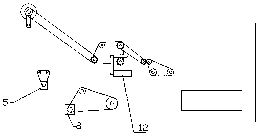
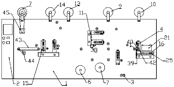
[0038] This implementation, as the basic embodiment of the present invention, discloses a compound molding machine for anorectal application. The specific structure is as follows: figure 1 As shown, it includes a frame 1, one end of the frame 1 is provided with a controller 2, and the frame 1 is provided with a plurality of guide rollers 3 located in the same plane, so as to ensure that the base layer is quickly and efficiently on the frame 1. Stable transmission, and at the same time, a horizontal processing surface is formed on the frame 1 to ensure the effective connection between various processing equipment, and the frame 1 is divided into cotton processing area, base layer laying area and laminating shearing area in sequence according to functions. Cotton shearing machine 4 and driving motor 5 are arranged in the cotton shearing area, and described cotton shearing machine 4 comprises support 22, and the support 22 is provided with die-cutting roller knife 24 by rolling be...

Embodiment 2

[0040] This embodiment is another preferred embodiment of the present invention, and its specific structure is as follows figure 1 As shown, the cotton shearer 4 inlet end is also provided with a cotton pressing machine 16, and the cotton pressing machine 16 is symmetrically provided with a left pressing roller 17 and a right pressing roller 18 that cooperate with each other, and the left pressing roller 17 and the right pressing roller 18 are arranged symmetrically. The right pressure rollers 18 are connected by transmission gears, and the transmission motor 5 is connected to any one of the left pressure rollers 27 or the right pressure rollers 28 through transmission gears; The left rotating shaft 19 and the right rotating shaft 20 that the roller 17 and the right pressing roller 18 are adapted to, a cotton pressing belt 21 is set between the left rotating shaft 19 and the left pressing roller 17, and a cotton pressing belt 21 is set between the right rotating shaft 20 and th...


PUM


Abstract

The invention discloses an anorectal patch composite forming machine comprising a frame. The frame comprises a cotton processing zone, a base laying zone and a fitting shearing zone. The cotton processing zone is provided with a cotton shearing machine and a transmission motor. The base laying zone comprises a base discharging roller and a scrap recycling roller, wherein the fitting shearing zoneis provided with a first shearing machine, a first discharging roller, a second discharging roller and a second shearing machine. Raw materials on each layer are laid by layers, and finally the rapidformation of the haemorrhoid patch can be achieved in the one-step press fit mode by the shearing machine. At the same time, the consistency between the layers is ensured to avoid the misalignment. Ashaping frame ensures the consistency of the central ridge of the patch and improves the forming effect, so that the therapeutic effect of the patch is improved.

Description

technical field [0001] The invention relates to the technical field of medical device production equipment, in particular to an anorectal application composite molding machine. Background technique [0002] At present, hemorrhoid applicators are often used clinically for daily maintenance of the window, but the hemorrhoid applicators in the prior art are usually set on a plane, which cannot fit perfectly with the groin of the human body, resulting in a loose fit between the applicator and the lesion. Even the lesion is not attached at all, which greatly affects the therapeutic effect of the application; thus, the company has developed a hemorrhoid application that can fit perfectly with the human body, but in the actual production process, it is found that due to the Due to the special structure, not only the production efficiency is low, but also the misalignment between the application layers is serious. At the same time, the bulge in the middle is of different sizes, and ...

Claims


Application Information

Patent Timeline
Patent Type & Authority Applications(China)
IPC IPC(8): A61F13/02
Inventor 郭亮唐迎波
Owner 四川艾医生医疗科技有限公司
Why Eureka
Try Eureka