Supercharge Your Innovation With Domain-Expert AI Agents!

Hydroelectric power generation device using multistage cascade structure

A technology of hydroelectric power generation device and drop, which is applied in the directions of hydropower generation, electromechanical device, structural connection, etc., can solve the problems of consumption, power generation efficiency decrease, and the strength of rotating waterwheel becomes smaller, and achieves the effect of simplifying the setting structure and minimizing the loss.

Inactive Publication Date: 2019-07-02
朴正治
View PDF7 Cites 0 Cited by
  • Summary
  • Abstract
  • Description
  • Claims
  • Application Information

AI Technical Summary

Problems solved by technology

[0005] However, the hydroelectric power generation device in the above-mentioned patent document has the following disadvantages: since a plurality of small waterwheels are provided, it is difficult to increase the drop rate of water applied to each waterwheel, thus causing the strength of the force to turn the waterwheels to also become small
[0006] In particular, the waterwheels arranged in multiple stages are connected so that one drive shaft is rotated through gears. Due to this structure, it is difficult to rotate the drive shaft only by the waterwheel located at the top during the initial drive. Causes the waterwheels to not rotate smoothly, which translates to a load on the waterwheels below, and therefore does not allow the waterwheels to rotate smoothly as a whole
[0007] Therefore, in the initial start-up process, it is necessary to provide rotational power by using a motor or the like so that the water wheel or the drive shaft can be rotated to make the water wheel rotate smoothly, and in order to continuously rotate the water wheel, it is necessary to use a water pump or the like to supply power to the water wheel. The uppermost waterwheel side is continuously supplied with water, so it will consume electricity for driving motors and water pumps, etc., which is directly related to the power generation efficiency of power generation by driving the generator, so there is also a problem that the power generation efficiency will decrease

Method used


Image

  • Hydroelectric power generation device using multistage cascade structure
  • Hydroelectric power generation device using multistage cascade structure
  • Hydroelectric power generation device using multistage cascade structure

Examples


Embodiment Construction

[0034] Hereinafter, the configuration and operation of the present invention will be described in more detail with reference to the drawings showing preferred embodiments.

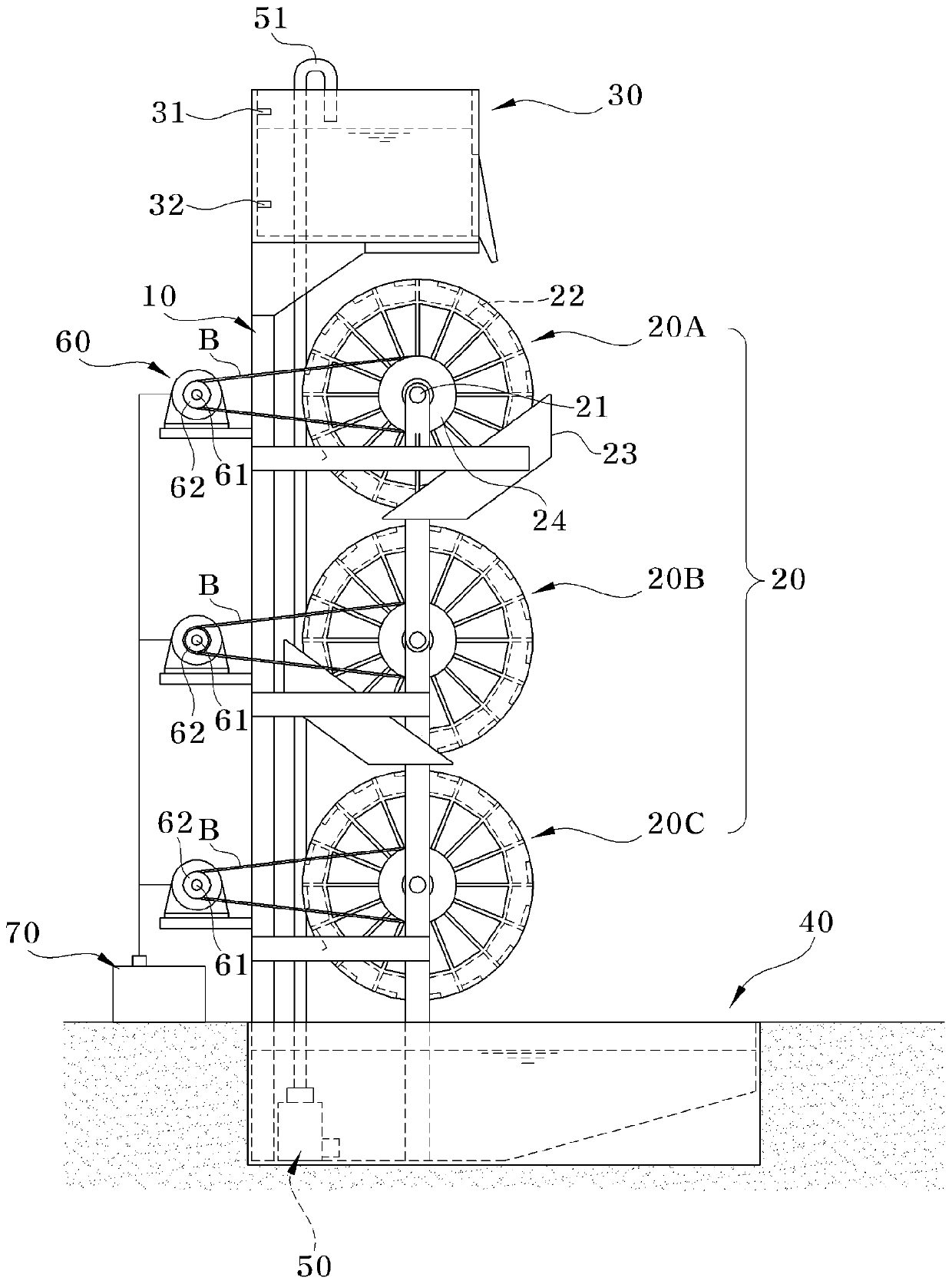
[0035] According to the hydroelectric power generation device utilizing the waterwheel arranged in multiple stages according to the present invention, a hydroelectric power generation device utilizing a multistage drop structure can be provided in which the waterwheel can be rotated without using a motor at the time of initial drive, It is also possible to make the waterwheel rotate smoothly, and to generate electricity continuously even if the water pump is not continuously operated. For this reason, such as figure 1 As shown, the hydroelectric power generation device of the present invention includes a bracket 10 , a waterwheel 20 , an upper water tank 30 , a lower water tank 40 , a water pump 50 , a generator 60 and a rechargeable battery 70 .

[0036] The stand 10 is erected on the ground with a predet...


PUM


Abstract

The present invention relates to a hydroelectric power generation device using a multistage cascade structure, comprising: a support (10) vertically installed and having a predetermined length; a plurality of water turbines (20), each of which includes a horizontal rotation shaft (21) rotatably installed on the support (10) and a plurality of buckets (22) radially arranged with reference to the rotation shaft (21); an upper and a lower reservoir (30, 40) respectively installed at an upper and a lower part of the support (10) so as to store a predetermined amount of water; a pump (50), installed in the lower reservoir (40), for supplying water stored in the lower reservoir (40) to the upper reservoir (30); a generator (60) installed on the rotation shaft of each of the plurality of water turbines (20); and a charging battery (70) for storing electricity produced by the generator (60). Thanks to such a configuration, the present invention can stably and effectively produce electricity.

Description

technical field [0001] The present invention relates to a hydroelectric power generation device using a multi-stage drop structure, and more particularly, to a hydroelectric power generation device using a multi-stage drop structure, that is, a plurality of waterwheels are arranged up and down, and the water passing through the upper part is driven along multiple The waterwheel falls down and turns the waterwheel to drive a generator, which generates electricity. Background technique [0002] Generally, various methods of generating electricity by using fire power, water power, wind power, and solar heat are known. Among them, devices using hydropower generation (hereinafter referred to as "hydroelectric power generation devices") have the advantages of less environmental pollution, simple structure, and low power generation costs. The advantages of other power generation devices are therefore widely used. [0003] Generally, a hydroelectric power generation device as descr...

Claims


Application Information

Patent Timeline
Patent Type & Authority Applications(China)
IPC IPC(8): F03B13/06F03B17/00F03B7/00F03B11/00F03B15/00
CPCF03B7/003F03B13/06F03B17/005F05B2240/40F05B2260/4021H02K7/1823H02K11/0094Y02E10/20Y02E60/16F03B11/008F03B15/00F05B2220/32F05B2220/706F03B7/00
Inventor 朴正治
Owner 朴正治
Features
  • R&D
  • Intellectual Property
  • Life Sciences
  • Materials
  • Tech Scout
  • Unparalleled Data Quality
  • Higher Quality Content
  • 60% Fewer Hallucinations
Learn More