Ship Tank System

A technology for storage tanks and ships, which is applied in ship propulsion, ship construction, ship parts, etc., and can solve problems such as limited space for ship installation

Active Publication Date: 2022-03-18
MAN ENERGY SOLUTIONS SA
View PDF5 Cites 0 Cited by
  • Summary
  • Abstract
  • Description
  • Claims
  • Application Information

AI Technical Summary

Problems solved by technology

This is disadvantageous because the installation space available on board is very limited

Method used


Image

  • Ship Tank System

Examples


Embodiment Construction

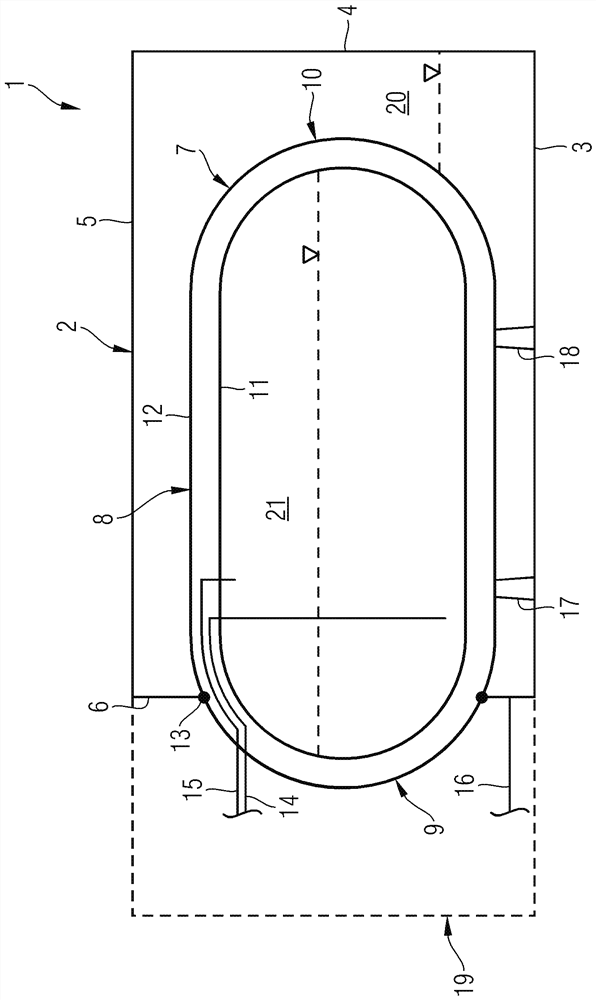
[0012] figure 1 The high schematic illustration of the ship storage tank system 1 constructed as a ship fuel storage system is present. In the exemplary embodiment shown, the ship storage tank system 1 has a first fuel storage tank 2, which provides an internal portion 20 of the fuel tank 20 that houses liquid flammable fuel (e.g., diesel or heavy fuel. Or residual oil). The first fuel storage tank 2 typically has a cubular geometry of the wall unit. figure 1 The four walls 3, 4, 5 and 6 of the first fuel storage tank 2 of this cube are drawn.

[0013] The ship fuel system [SiC] 1 also has a second fuel storage tank 7 that houses a gaseous non-flammable fuel (especially natural gas), in particular in the fuel storage interior 21 of the second fuel storage case 7. The second fuel storage case 7 preferably contains a gaseous non-flammable fuel in a liquefied form at low temperatures.

[0014] In the sense of the present invention, the second fuel storage tank 7 is closely to the fi...


PUM


Abstract

A marine tank system (1) with a first tank, preferably a first fuel tank (2), containing a liquid flammable fuel or alternatively water, with a second fuel containing a gaseous non-flammable fuel A tank (7), wherein the second fuel tank (7) is interconnected or integrated into the first, preferably first, fuel tank (2) such that the first, preferably first fuel tank (2) Encloses at least a section of the second fuel tank ( 7 ) on the outside.

Description

Technical field [0001] The present invention relates to a marine storage tank system. Background technique [0002] The use of a binary fuel motor is known in practice. In a binary fuel motor, liquid flammable fuels (e.g., diesel) can be used in the first mode of operation, and gaseous non-flammable fuels (eg, natural gas) can be used in the second mode of operation. In the second mode of operation of the double fuel motor, the poor, non-flammable gas-air mixture is typically introduced into the motor of the motor, and is ignited by ignition of flammable fluid also introduced into the cylinder. . [0003] Liquid flammable fuels for the first mode of operation are housed in the first fuel storage tank. The gaseous non-flammable fuel is accommodated in the second fuel storage tank, preferably in a liquefied form. Different fuel storage tanks require many installation spaces. This is unfavorable because the installation space available on the ship is limited. Inventive content [0...

Claims


Application Information

Patent Timeline
Patent Type & Authority Patents(China)
IPC IPC(8): B63B17/00B63H21/38
CPCB63B17/0027B63H21/38F17C3/00F17C13/082F17C2201/0109F17C2201/0157F17C2201/035F17C2201/054F17C2203/0391F17C2203/0629F17C2205/0149F17C2205/018F17C2205/0192F17C2221/033F17C2223/0161F17C2223/033F17C2223/043F17C2225/047F17C2270/0105B63B25/14Y02T10/30B63B11/04F02D19/06F02D19/08B60K15/03B65D88/02F17C3/08B63B25/16B63B73/20B63B73/43F17C2201/0104
Inventor M.贝施坦
Owner MAN ENERGY SOLUTIONS SA
Why Eureka
Try Eureka