Waste gas treatment device and waste gas treatment device based on liquid nitrogen condensation

A waste gas treatment device and waste gas technology, which are applied in gas treatment, separation methods, chemical instruments and methods, etc., can solve the problems of no process and scheme, fire explosion, polluting gas discharge, etc., to prevent uncontrolled escape and prevent safety Accidents, the effect of achieving environmentally friendly emissions

Inactive Publication Date: 2020-03-10
CHINA PETROLEUM & CHEM CORP +1
View PDF6 Cites 2 Cited by
  • Summary
  • Abstract
  • Description
  • Claims
  • Application Information

AI Technical Summary

Problems solved by technology

[0003] However, in the process of petroleum refining, storage, and transportation, there are one-time tail gas discharge construction operations, such as cleaning of crude oil storage tanks, cleaning of storage tanks in gas stations, and hot nitrogen purging of activated carbon in adsorption devices, etc. Avoided construction operations also bring high-concentration and large-volume pollutant gas emissions
At present, there is no suitable process and plan for the treatment of this kind of one-time polluting gas emissions. Therefore, most of the polluting gases generated by such construction operations are directly discharged into the atmosphere.
[0004] Therefore, during the construction operation of one-time pollutant gas discharge, the discharged oil and gas will enter the air, and static electricity and electric sparks will cause disasters such as fire and explosion, which seriously affects the personal safety and health of residents around the gas station. At the same time, it also violates the relevant provisions of the existing national environmental protection laws and regulations, and is no longer suitable for the requirements of modern operations.
In recent years, due to the uncontrolled escape of oil and gas, there have been many safety production accidents in which oil and gas flash explosions caused casualties

Method used


Image

  • Waste gas treatment device and waste gas treatment device based on liquid nitrogen condensation

Examples


Embodiment 1

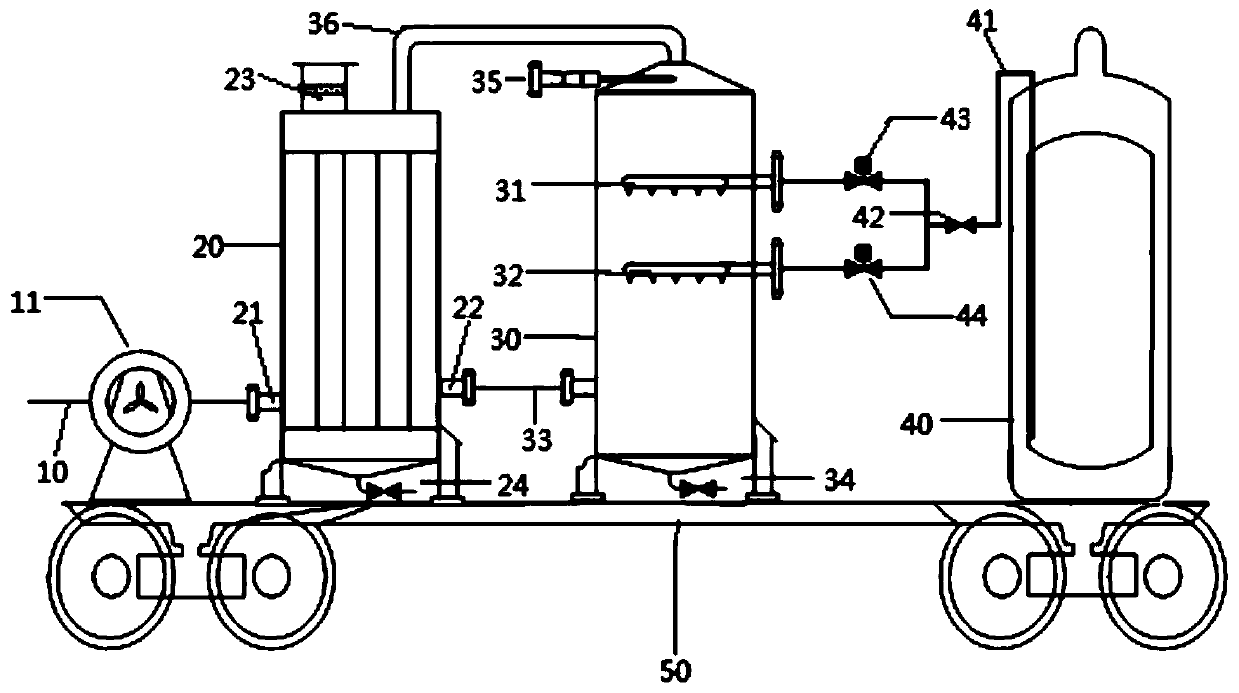
[0071] Such as figure 1 As shown, the exhaust gas treatment device includes a suction pipe 10 , a fan 11 , a first condensation tank 20 , a second condensation tank 30 and a liquid nitrogen storage tank 40 connected in sequence.

[0072] Wherein, the first condensing tank 20 is provided with a waste gas inlet 21 and a waste gas outlet 22, the waste gas inlet 21 and the waste gas outlet 22 are all arranged at the bottom of the first condensation tank 20, the waste gas inlet 21 is connected with the suction pipe 10, and the waste gas outlet 22 communicates with the inside of the second condensation tank 30 through the gas delivery pipe 33 connected to the bottom of the second condensation tank 30 . The inside of the first condensation tank 20 includes a condensing structure, the condensing structure is a cooler, the shell side inlet of the cooler is connected to the waste gas inlet 21, the shell side outlet is connected to the waste gas outlet 22, and the tube side inlet is conn...

Embodiment 2

[0080] The waste gas treatment device adopts the same structure as that of Example 1.

[0081] In addition, in the first condensation tank 20, the operating conditions of the cooler are as follows: the inlet temperature of the tube side is minus 70°C, the outlet temperature of the tube side is minus 35°C, and the pressure is 2kpa; the inlet temperature of the shell side is normal temperature, and the outlet temperature of the shell side is The temperature is minus 35°C and the pressure is 3kp. In the second condensation tank 30, the temperature inside the second condensation tank 30 is maintained at minus 90°C.

[0082] Based on the exhaust gas treatment device of the above preferred embodiment, and under the above operating conditions, when the VOCs exhaust gas concentration at the exhaust gas inlet 21 is 34% VOL, the VOCs exhaust gas concentration at the tube side outlet is 50% LEL, and the exhaust gas treatment efficiency is 98.93%.

Embodiment 3

[0084] The waste gas treatment device adopts the same structure as that of Example 1.

[0085] In addition, in the first condensation tank 20, the operating conditions of the cooler are as follows: the inlet temperature of the tube side is minus 80°C, the outlet temperature of the tube side is minus 40°C, and the pressure is 2kpa; the inlet temperature of the shell side is normal temperature, and the outlet temperature of the shell side is The temperature is minus 35°C and the pressure is 3kp. In the second condensation tank 30, the temperature inside the second condensation tank 30 is maintained at minus 90°C.

[0086] Based on the above exhaust gas treatment device and under the above operating conditions, when the VOCs exhaust gas concentration at the exhaust gas inlet 21 is 35% VOL, the VOCs exhaust gas concentration at the tube side outlet is 25% LEL, and the exhaust gas treatment efficiency is 99.14%.


PUM


Abstract

The invention relates to technical field of waste gas treatment and discloses a waste gas treatment device and a waste gas treatment device based on liquid nitrogen condensation. The waste gas treatment device includes: a first condensation tank (20), in which a condensation structure is arranged, and on which an oil gas inlet (21) and an oil gas outlet (22) are formed; a second condensation tank(30), in which a sprayer is formed, wherein a gas feeding pipe (33) is connected to the side wall of the lower part and a gas discharge pipe (36) is connected to the top, the gas feeding pipe (33) being connected to the oil gas outlet (22); and a liquid nitrogen storage tank (40) connected to the sprayer via a liquid nitrogen pipeline (41). The waste gas treatment device allows two-stage condensation on waste gas, thereby purifying the discharged VOCs waste gas from a construction operation process of one-time pollution gas emission. The device can prevent uncontrolled escape of the pollutiongas, so that the device not only prevents safety accidents but also achieves environment-friendly discharge.

Description

technical field [0001] The invention relates to the technical field of waste gas treatment, in particular to a liquid nitrogen condensation-based waste gas treatment device and a waste gas treatment method for treating disposable tail gas. Background technique [0002] Petrochemical companies often produce one-time exhaust (VOCs exhaust) emissions during petroleum refining, storage, and transportation. For such fixed places, fixed oil and gas recovery and treatment devices have matured and the market is gradually saturated. For example, the adsorption and absorption method oil gas recovery device used in the oil depot, the mechanical refrigeration adsorption method oil gas recovery device used in the wharf, and the absorption adsorption method catalytic oxidation device used in the refining and chemical enterprise. [0003] However, in the process of petroleum refining, storage, and transportation, there are one-time tail gas discharge construction operations, such as clean...

Claims


Application Information

Patent Timeline
Patent Type & Authority Applications(China)
IPC IPC(8): B01D53/44B01D53/78
CPCB01D53/44B01D53/78B01D2251/2062B01D2257/708
Inventor 程龙军陶彬单晓雯张健中宫中昊于辉
Owner CHINA PETROLEUM & CHEM CORP
Why Eureka
Try Eureka