Ship tank system

A technology for storage tanks and ships, which is applied in ship propulsion, ship construction, ship parts, etc., and can solve problems such as limited space for ship installation

Active Publication Date: 2019-07-05
MAN ENERGY SOLUTIONS SE
View PDF5 Cites 0 Cited by
  • Summary
  • Abstract
  • Description
  • Claims
  • Application Information

AI Technical Summary

Problems solved by technology

This is disadvantageous because the installa

Method used


Image

  • Ship tank system
  • Ship tank system

Examples


Embodiment Construction

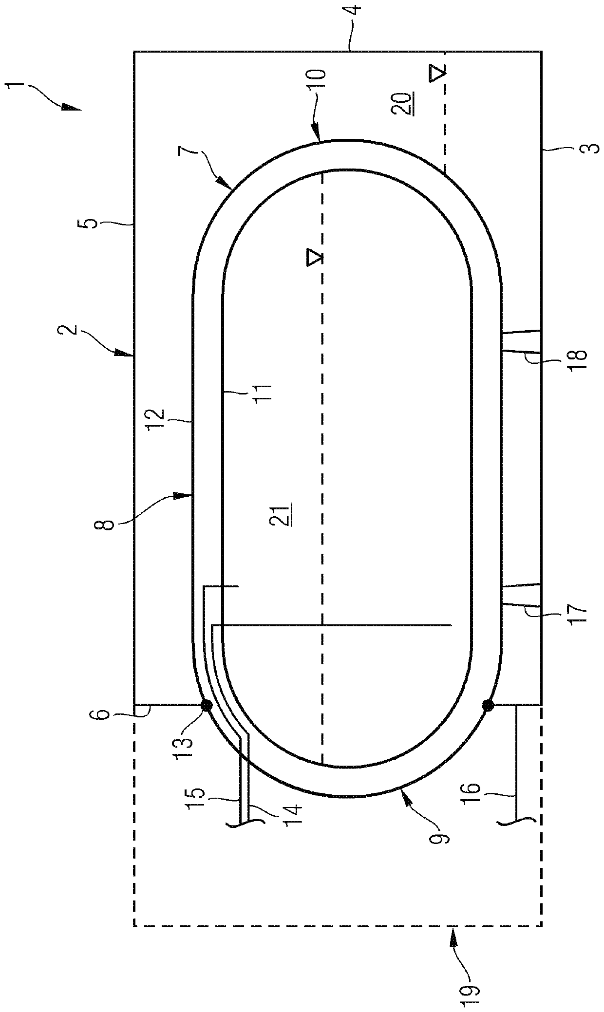
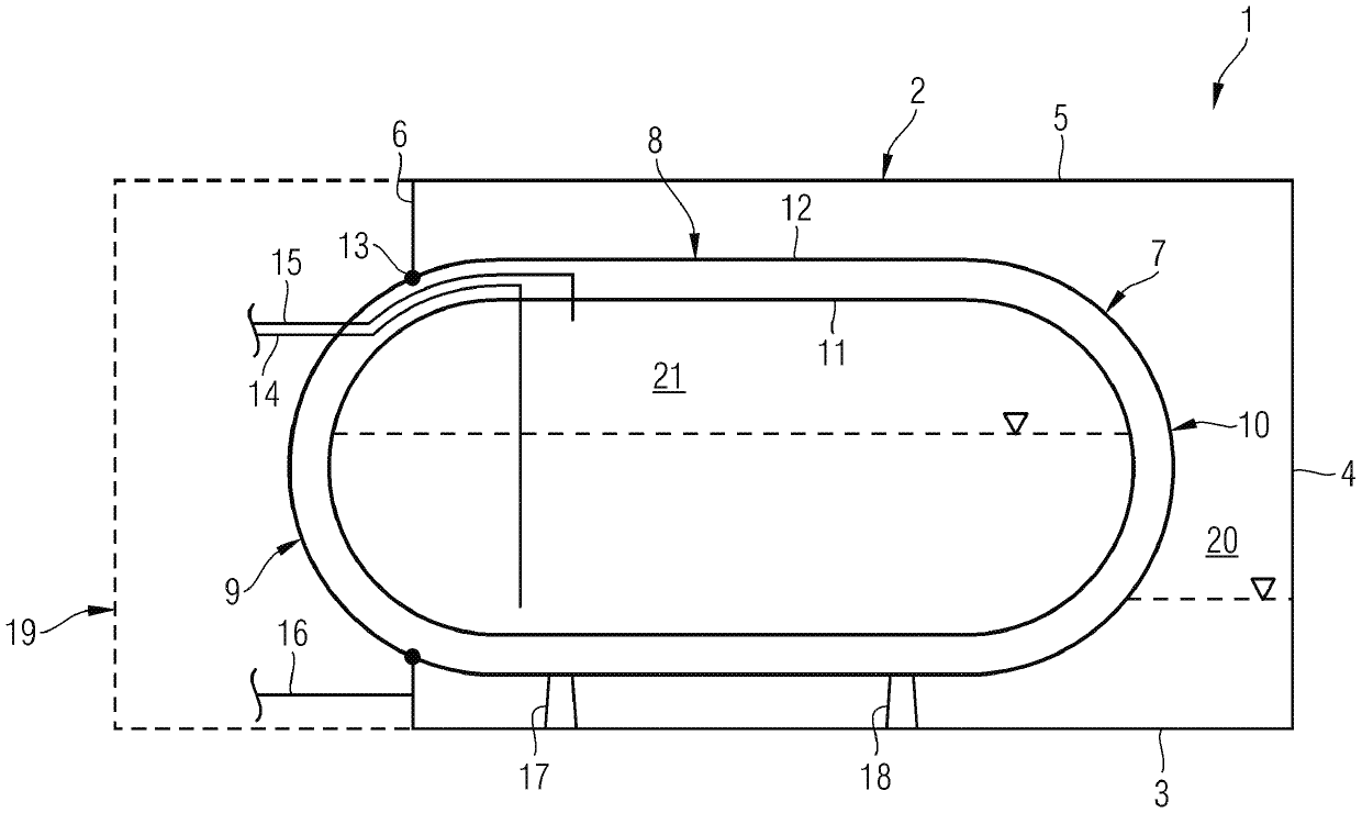
[0012] figure 1 A highly schematic illustration of a marine tank system 1 configured as a marine fuel tank system is presented. In the exemplary embodiment shown, the marine tank system 1 has a first fuel tank 2 providing a fuel tank interior 20 containing a liquid combustible fuel (eg diesel or heavy fuel or residual oil). The first fuel tank 2 typically has a cuboidal geometry delimited by walls. figure 1 The four walls 3, 4, 5 and 6 of this cubic first fuel tank 2 are drawn.

[0013] The ship fuel system [sic] 1 also has a second fuel tank 7 containing a gaseous non-flammable fuel, in particular natural gas, in particular in a fuel tank interior 21 of the second fuel tank 7 . The second fuel tank 7 preferably contains a gaseous non-flammable fuel in liquefied form at low temperature.

[0014] Within the meaning of the invention, the second fuel tank 7 is attached or integrated into the first fuel tank 2 , in particular such that the first fuel tank 2 externally surround...


PUM


Abstract

A marine tank system (1) is provided with a first tank, preferably a first fuel tank (2), containing a liquid combustible fuel or alternatively water, and a second fuel tank (7) containing a gaseous non-combustible fuel, wherein the second fuel tank (7) is interconnected or integrated into the first tank, preferably the first fuel tank (2), such that the first tank, preferably the first fuel tank(2) surrounds at least a section of the second fuel tank (7) on the outside.

Description

technical field [0001] The invention relates to a ship storage tank system. Background technique [0002] The use of dual fuel motors on ships is known from practice. In a dual fuel motor, a liquid flammable fuel (eg, diesel) may be used in the first mode of operation and a gaseous non-flammable fuel (eg, natural gas) may be used in the second mode of operation. In the second mode of operation of the dual fuel motor, a generally lean, non-flammable gas-air mixture is introduced into the cylinders of the motor and ignition is ignited by the ignition energy of a flammable liquid ignition fluid also introduced into the cylinders . [0003] Liquid combustible fuel for the first mode of operation is contained in the first fuel tank. Gaseous non-flammable fuel is contained in the second fuel tank, preferably in liquefied form. The different fuel tanks require a lot of installation space. This is disadvantageous since the installation space available on ships is very limited. ...

Claims


Application Information

Patent Timeline
IPC IPC(8): B63B17/00B63H21/38
CPCB63B17/0027B63H21/38F17C3/00F17C13/082F17C2201/0109F17C2201/0157F17C2201/035F17C2201/054F17C2203/0391F17C2203/0629F17C2205/0149F17C2205/018F17C2205/0192F17C2221/033F17C2223/0161F17C2223/033F17C2223/043F17C2225/047F17C2270/0105B63B25/14Y02T10/30B63B11/04F02D19/06F02D19/08B60K15/03B65D88/02F17C3/08B63B25/16B63B73/20B63B73/43F17C2201/0104
Inventor M.贝施坦
Owner MAN ENERGY SOLUTIONS SE
Why Eureka
Try Eureka