Novel inner ring wall structure

A ring wall, a new type of technology, applied in the direction of furnace type, furnace, vertical furnace, etc., can solve the problems of aggravating the wall, not having a fixing function, and not solving the stability of the inner ring wall from the principle, so as to improve Stability and the effect of prolonging the service life

Pending Publication Date: 2019-07-16
ACRE COKING & REFRACTORY ENG CONSULTING CORP DALIAN MCC
View PDF0 Cites 0 Cited by
  • Summary
  • Abstract
  • Description
  • Claims
  • Application Information

AI Technical Summary

Problems solved by technology

Although this method can enhance the integrity of the inner ring wall, it does not solve the stability problem of the inner ring wall in principle. The main reasons are as follows: 1) In the design, the inner ring wall can be simplified The inner ring wall is only fixed at the bottom, because there is a sliding layer at the bottom of the inner ring wall, and the top has no fixing function; 2) The inner ring wall bears the lateral pressure of the filling material in the furnace on the wall, once the wall deforms and tilts outward Then the lateral pressure and material gravity will continue to aggravate the outward inclination of the wall; 3) In the working state, the working temperature of the inner ring wall is as high as 1000°C, and the refractory material of the wall will have a thermal expansion of about 5‰ at this temperature, while When the CDQ oven is shut down for maintenance, the refractory material of the wall will shrink to the original length, and the accumulated shrinkage will be concentrated and released at the weak joints of the bricks, causing the wall to crack, which will not recover automatically and become Weaknesses in the wall where it is more likely to cause flare

Method used


Image

  • Novel inner ring wall structure
  • Novel inner ring wall structure
  • Novel inner ring wall structure

Examples


Embodiment Construction

[0032] The specific embodiment of the present invention will be further described below in conjunction with accompanying drawing:

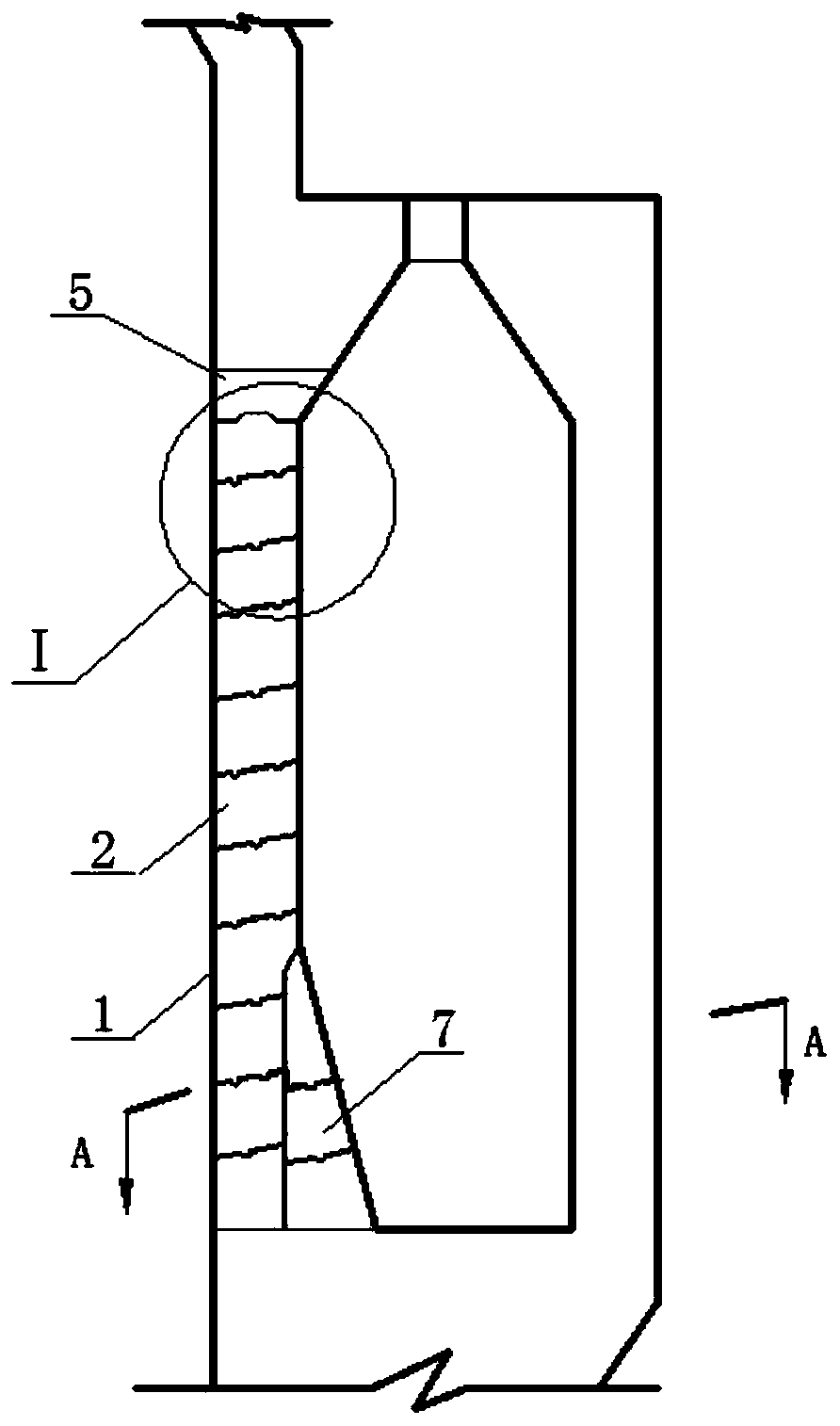
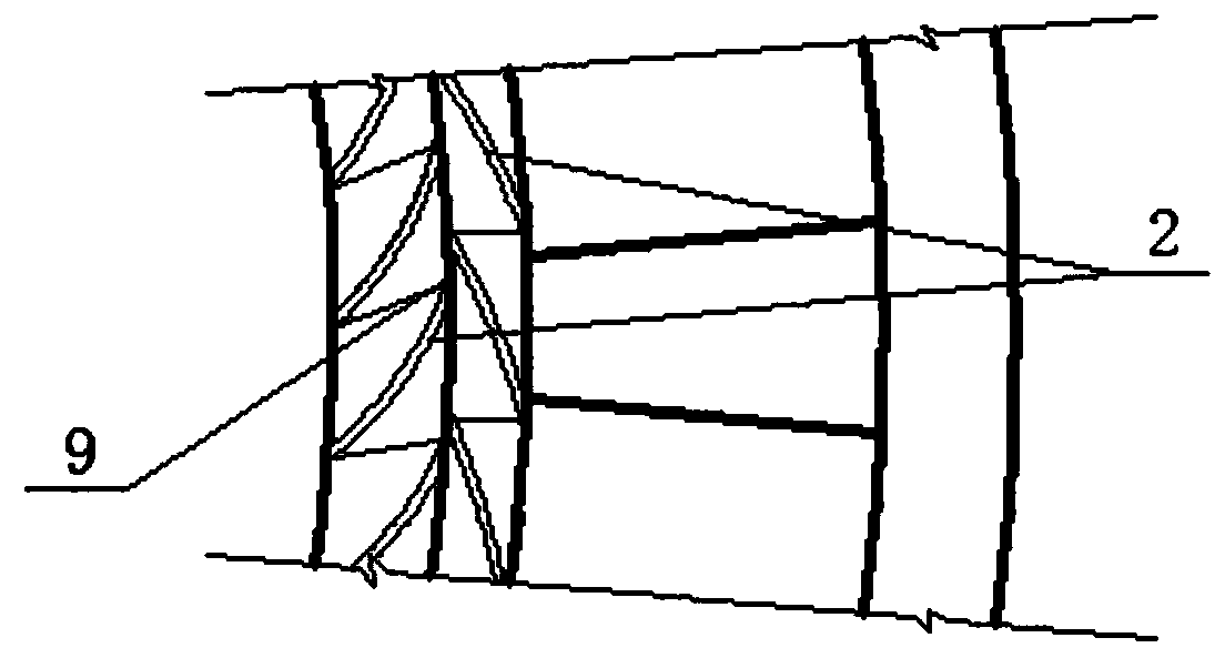
[0033] like figure 1 , figure 2 , Figure 4 As shown, a new type of inner ring wall structure described in the present invention includes an inner ring wall 1 located in the annular air duct area of ​​a gas-solid heat exchange shaft furnace; The material block 2 is built by masonry. The upper surface and the lower surface of the refractory material block 2 are slopes inclined outward and upward, and two adjacent layers of refractory material blocks 2 are connected by a groove tongue structure.

[0034] like image 3 , Figure 5 As shown, the matched brick grooves 3 and brick tongues 4 that make up the tongue structure have a spiral structure that diverges outward.

[0035] like figure 1 , Figure 4 , Image 6 As shown, the upper surface of the refractory block 2 on the topmost layer of the inner ring wall 1 is provided with an arc-shaped ...


PUM


Abstract

The invention relates to a novel inner ring wall structure. The novel inner ring wall structure comprises an inner ring wall arranged in an annular air duct region of a gas-solid heat exchange type vertical furnace; the inner ring wall is formed by building a plurality of refractory material building blocks which are arranged in a high direction, the upper surface and the lower surface of the refractory material building blocks are inclined planes inclined outwards and upwards, and every two adjacent refractory material building blocks are in occlusion connection through a groove tongue structure; and a brick groove and a brick tongue matched with the groove tongue structure is formed, and the has a vortex-shaped structure which is outwards diffused. According to the novel inner ring wallstructure, the inclined surface and the vortex-shaped brick groove and the brick tongue are formed in the refractory material building blocks forming the inner ring wall, so that the inner ring wall can be subjected to displacement outwards when the inner ring wall bears the lateral force, the annular sliding structure at the top of the inner ring wall absorbs the rotating displacement generated by expansion from the lower part, so that the inner ring wall has a self-stabilizing function, the influence of thermal expansion and lateral force on the wall body is effectively resisted, and the service life of the inner ring wall is prolonged.

Description

technical field [0001] The invention relates to a furnace body structure of a gas-solid heat exchange type shaft furnace, in particular to a novel inner ring wall structure. Background technique [0002] In the furnace body structure of a gas-solid heat exchange shaft furnace such as a CDQ oven, the inner ring wall located in the annular air duct area is prone to damage and outward tilt. The reasons include the following points: 1) When the materials in the furnace fall The impact of the inner ring wall; 2) the lateral force extrusion generated after the furnace is filled with materials; 3) the cracking of the inner ring wall due to thermal expansion during repeated shutdowns for maintenance. [0003] At present, the method of strengthening the structural strength of the annular air duct is often to add a complex groove tongue structure on the wall bricks of the inner ring wall, so that the brick walls are fixed in their respective positions. Although this method can enhanc...

Claims


Application Information

Patent Timeline
IPC IPC(8): F27B1/10F27D1/04
CPCF27B1/10F27D1/04
Inventor景殿策
OwnerACRE COKING & REFRACTORY ENG CONSULTING CORP DALIAN MCC