Al technical title is built by PatSnap Al team. It summarizes the technical point description of the patent document.
A welding production line, robot intelligence technology, applied in the direction of welding equipment, auxiliary equipment, auxiliary welding equipment, etc., can solve the problems of automation, large labor force, time-consuming and labor-intensive, etc., to increase speed, reduce labor intensity, and improve convenience Effect
Active Publication Date: 2021-06-04
中山叁迪智能设备有限公司
View PDF0 Cites 0 Cited by
Summary
Abstract
Description
Claims
Application Information
AI Technical Summary
This helps you quickly interpret patents by identifying the three key elements:
Problems solved by technology
Method used
Benefits of technology
Problems solved by technology
[0003] In the robot welding production line, due to the use of fully automated welding technology, the welding quality and production efficiency are greatly improved, and it also saves a lot of expenses for the enterprise. However, during the welding process of the welding robot, the weld position surface There is a large amount of welding slag and oxide skin, so it is necessary to knock it off and then check the quality of the welding position. At present, it is mainly carried out by manual knocking, and it is difficult to automate the entire process. At the same time, it is necessary to remove The process of welding slag requires a lot of labor and is time-consuming and labor-intensive
Method used
Image
Click on the blue label to locate the original text in one second.
Reading with bidirectional positioning of images and text.
Examples
Embodiment Construction
[0024] The following will clearly and completely describe the technical solutions in the embodiments of the present invention with reference to the accompanying drawings in the embodiments of the present invention. Obviously, the described embodiments are only some, not all, embodiments of the present invention. Based on the embodiments of the present invention, all other embodiments obtained by persons of ordinary skill in the art without making creative efforts belong to the protection scope of the present invention.
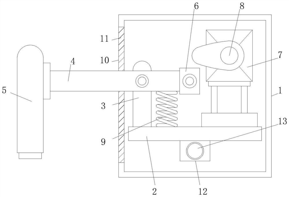
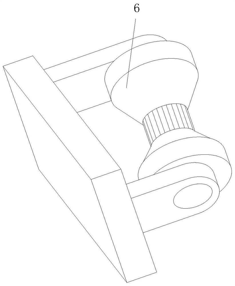
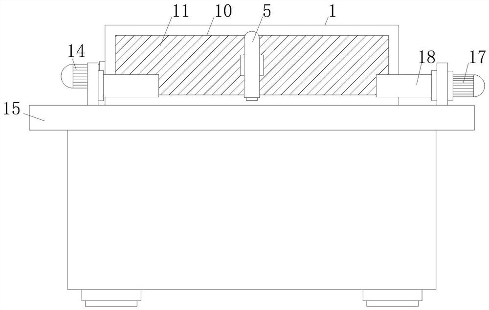
[0025] see Figure 1-4 , the present invention provides a technical solution: a robotic intelligent welding production line, including a mounting box 1, a movable plate 2, a support plate 3, a connecting rod 4, a beating head 5, a contact roller 6, a driving motor 7, and a cam 8 , return spring 9, dust-proof clump hair 11, ball nut 12, ball screw 13, drive motor 14, welding table 15, chip bucket 16, rotating motor 17 and clamp 18, movable plate 2 is located in...
PUM
Abstract
The present invention relates to the technical field of welding production line, in particular to a robotic intelligent welding production line, which includes a mounting box, a movable plate, a support plate, a connecting rod, a beating head, a contact roller, a driving motor, a cam, a return spring, and a dust-proof cluster. hair, ball nut, ball screw, drive motor, chip removal bucket, rotating motor and fixture, the movable plate is located inside the installation box, and the middle position on the left side of the top of the movable plate is fixedly connected with the bottom of the support plate. The left end of the connecting rod is fixedly connected to the top on the right side of the beating head, and the right end of the connecting rod extends to the inside of the installation box. The invention achieves the purpose of knocking and removing the welding slag at the welding place by the beating head, thereby replacing the manual removal method, and the whole process complements the automatic welding, reduces the manual participation in the work mode, and makes the whole welding line autonomous The effect, which in turn reduces the labor intensity and improves the welding speed.
Description
technical field [0001] The invention relates to the technical field of welding production line, in particular to a robot intelligent welding production line. Background technique [0002] Welding robots mainly include two parts: robots and welding equipment. The robot consists of a robot body and a control cabinet (hardware and software). For intelligent robots, there should also be sensing systems, such as laser or camera sensors and their control devices. The welding robots produced in various countries in the world are basically joint robots, and most of them have 6 axes. Among them, the 1, 2, and 3 axes can send the end tool to different spatial positions, while the 4, 5, and 6 axes can solve different requirements for the tool posture. [0003] In the robot welding production line, due to the use of fully automated welding technology, the welding quality and production efficiency are greatly improved, and it also saves a lot of expenses for the enterprise. However, wh...
Claims
Application Information
Patent Timeline
Application Date:The date an application was filed.
Publication Date:The date a patent or application was officially published.
First Publication Date:The earliest publication date of a patent with the same application number.
Issue Date:Publication date of the patent grant document.
PCT Entry Date:The Entry date of PCT National Phase.
Estimated Expiry Date:The statutory expiry date of a patent right according to the Patent Law, and it is the longest term of protection that the patent right can achieve without the termination of the patent right due to other reasons(Term extension factor has been taken into account ).
Invalid Date:Actual expiry date is based on effective date or publication date of legal transaction data of invalid patent.