Check patentability & draft patents in minutes with Patsnap Eureka AI!

A hollow glass inert gas inflator

A technology of inert gas and inflator, which is applied in the direction of construction, building components, building structures, etc., can solve the problems of small manual operation space for external operators, inability to carry out small batch production, and increase damage to insulating glass, etc., to achieve rich functions, Adjustment and replacement at will, high degree of modularity

Active Publication Date: 2020-05-12
南通金蝴蝶节能科技有限公司
View PDF5 Cites 1 Cited by
  • Summary
  • Abstract
  • Description
  • Claims
  • Application Information

AI Technical Summary

Problems solved by technology

[0002] As we all know, hollow glass is a kind of good heat insulation, sound insulation and beautiful building material. It is generally produced by filling two pieces of glass with inert gas and sealing them with adhesive such as glue; the traditional production process of hollow glass is complicated, especially It is in the link of inert gas filling. In order to keep no air in the insulating glass, it is often necessary to complete the production in a larger inert air, which will result in higher costs for the production of insulating glass, and external operators manually operate the space. It is too small to carry out small-batch production; in addition, the traditional insulating glass is sealed as a separate production process, and the insulating glass needs to be transferred as a whole when sealing, which increases the damage to the insulating glass during transportation. There is a large production interval between the process of filling inert gas and sealing, and the production efficiency is low; therefore, it is necessary to design an inert gas inflator for insulating glass to solve the above problems

Method used


Image

  • A hollow glass inert gas inflator
  • A hollow glass inert gas inflator
  • A hollow glass inert gas inflator

Examples


Embodiment Construction

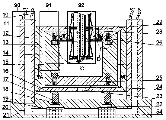
[0024] Combine below Figure 1-5 The present invention is described in detail, and for convenience of description, the orientations mentioned below are now stipulated as follows: figure 1 The up, down, left, right, front and back directions of the projection relationship itself are the same.

[0025] combined with Figure 1-5 The hollow glass inert gas inflator includes a base 21, and the top surface of the base 21 is symmetrically fixed with a metal plate 11;

[0026] A side frame 13 is installed symmetrically slidingly between the two metal plates 11, a lower frame 25 is fixed below the two side frames 13, and an upper frame 26 is fixed above the two side frames 13. There is a gap between the upper frame 26, the lower frame 25 and the side frame 13, and the installation cavity formed between the upper frame 26, the lower frame 25 and the side frame 13 is provided with a The fixing mechanism 91 of the glass plate 15 is installed symmetrically front and back in the installa...


PUM


Abstract

The invention provides a hollow glass inert glass inflator, including a base. The top surface of the base is symmetrically and fixedly provided with metal plates in a left and right mode, side edge frames are symmetrically and slidably installed between the two metal plates in a left and right mode, the lower parts of the side edge frames are fixedly provided with lower edge frames, the upper parts of the side edge frames are fixedly provided with upper edge frames, and gaps are formed between the lower edge frames, the lower edge frames and the side edge frames. According to the hollow glassinert gas inflator, hollow glass can be filled with inert gases, glue is used for sealing the hollow glass, the modularity degree of the device is high, parts can be adjusted and replaced at will, flexibility and variability are achieved, operation is simple and clear, at the same time, the side edge frames are precooled by a cooling mechanism, solidification of the glue can be accelerated by thecooling mechanism at the same time, production time is reduced, reaction of the device is sensitive, the function is rich, in addition, the glue cannot overflow while blocking the gaps, and the quality of the hollow glass with the inert gases is high.

Description

technical field [0001] The invention relates to the field of hollow glass production, in particular to an inert gas inflator for hollow glass. Background technique [0002] As we all know, hollow glass is a kind of good heat insulation, sound insulation and beautiful building material. It is generally produced by filling two pieces of glass with inert gas and sealing them with adhesive such as glue; the traditional production process of hollow glass is complicated, especially It is in the link of inert gas filling. In order to keep no air in the insulating glass, it is often necessary to complete the production in a larger inert air, which will result in higher costs for the production of insulating glass, and external operators manually operate the space. It is too small to carry out small-batch production; in addition, the traditional insulating glass is sealed as a separate production process, and the insulating glass needs to be transferred as a whole when sealing, which...

Claims


Application Information

Patent Timeline
Patent Type & Authority Patents(China)
IPC IPC(8): E06B3/673E06B3/677
CPCE06B3/673E06B3/67343E06B3/6775
Inventor 杨明华
Owner 南通金蝴蝶节能科技有限公司
Features
  • R&D
  • Intellectual Property
  • Life Sciences
  • Materials
  • Tech Scout
  • Unparalleled Data Quality
  • Higher Quality Content
  • 60% Fewer Hallucinations
Learn More