Supercharge Your Innovation With Domain-Expert AI Agents!

A photoelastic instrument auxiliary installer

A technology of photoelasticity and installation device, which is applied to chemical instruments and methods, cleaning methods and utensils, cleaning methods using tools, etc., can solve the problems of lens and gyroscope round head falling off, etc. The effect of easy installation

Inactive Publication Date: 2020-12-18
铜陵有色股份天马山黄金矿业有限公司
View PDF8 Cites 0 Cited by
  • Summary
  • Abstract
  • Description
  • Claims
  • Application Information

AI Technical Summary

Problems solved by technology

[0005] In order to overcome the shortcomings of using a round wooden stick on the top of the head, excessive force will easily cause the lens and the round head of the gyroscope to fall off, causing the concrete mortar to flow out along the gap between the rock and the instrument, and the concrete mortar that comes out will cover the lens of the instrument. Technical problem : Provide a photoelastic instrument auxiliary installer that can quickly install and ensure the cleanliness of the photoelastic strain gauge lens

Method used


Image

  • A photoelastic instrument auxiliary installer
  • A photoelastic instrument auxiliary installer
  • A photoelastic instrument auxiliary installer

Examples


Embodiment 1

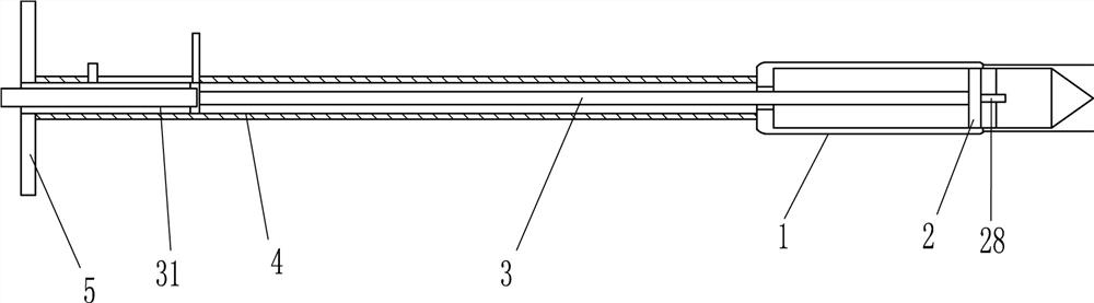
[0021] Refer to attached figure 1 , attached figure 2 And attached image 3 , a photoelastic instrument auxiliary installer, including a cylindrical sleeve 1, a clamping device 2, a push rod 3, a hexagonal rotating rod 31, a sleeve 4 and an annular push plate 5, and the cylindrical sleeve 1 passes through a chute slider The sliding type is provided with a clamping device 2, and the clamping device 2 is used to fix the photoelastic instrument. The cylindrical sleeve 1 is provided with a sleeve 4, and the sliding type is provided with a push rod 3 inside the sleeve 4, and the push rod 3 is connected with the clamp. Tightening device 2 is connected, and sleeve pipe 4 other end is provided with annular push plate 5, has hexagonal groove on push rod 3, and hexagonal turning rod 31 snaps in the hexagonal groove, and hexagonal turning rod 31 passes through annular pushing plate 5.

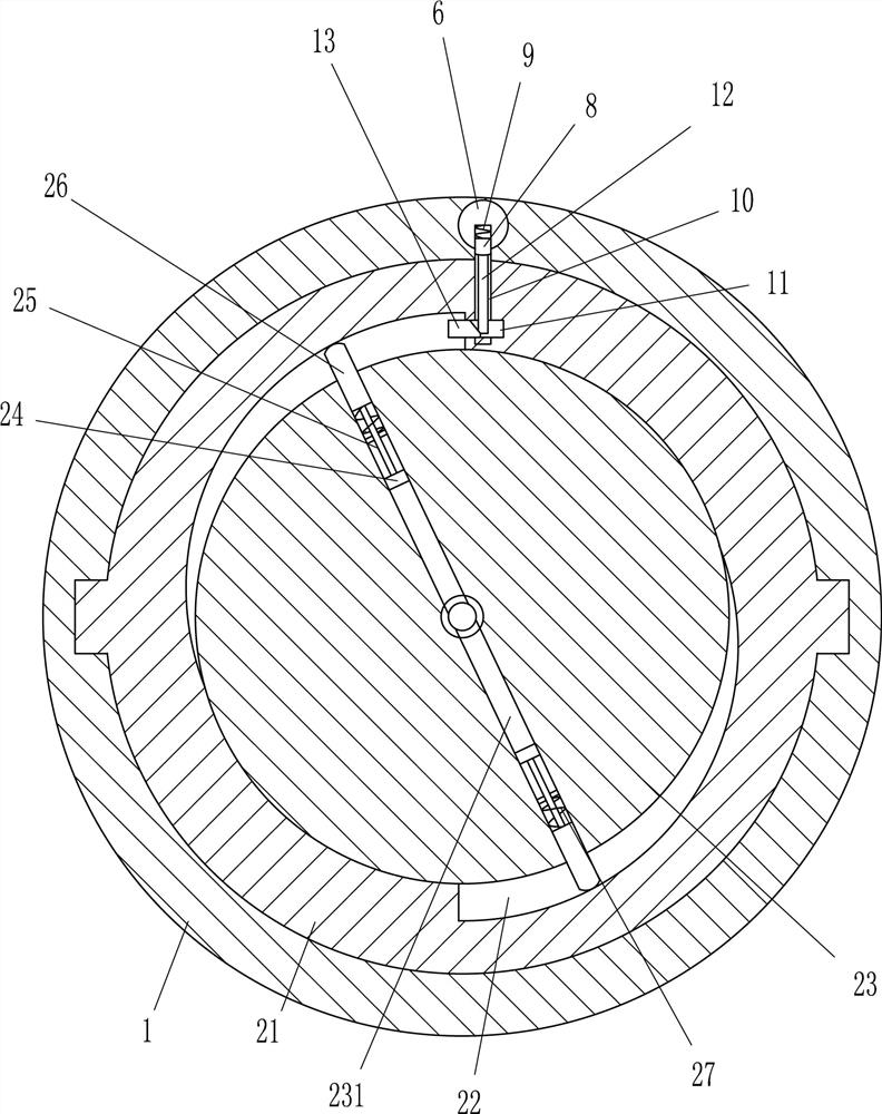
[0022] The clamping device 2 includes a cylindrical slide 21, a cylindrical block 23, a cylindrical...

Embodiment 2

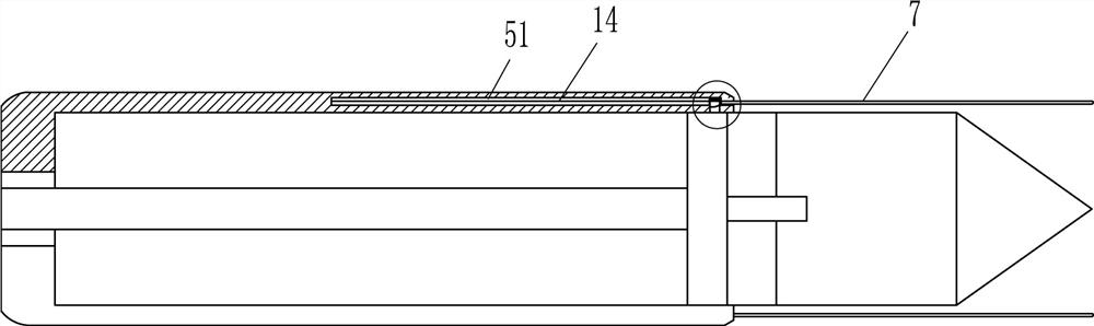
[0025] Refer to attached figure 1 , attached figure 2 , attached image 3 , attached Figure 4 , attached Figure 5 And attached Image 6, on the basis of Embodiment 1, it also includes a sliding block 6, a thimble 7, a second wedge 8, a third elastic member 9, a second push rod 12, a third wedge 13 and an elastic cord 14, and a cylindrical sleeve 1 is symmetrically opened with a word groove 51, and a sliding block 6 is arranged in the word groove 51, and a thimble 7 is arranged on the sliding block 6, and a mounting groove is opened on the side of the sliding block 6 near the cylindrical sliding tube 21, and the installation A second wedge-shaped block 8 is provided slidingly in the groove, and a third elastic member 9 is arranged between the second wedge-shaped block 8 and the installation groove. The third elastic member 9 is a compression spring. The through hole 10 and the tank body 11, the through hole 10 communicates with the tank body 11, the tank body 11 communi...


PUM


Abstract

The invention belongs to the technical field of ground pressure monitoring, and in particular relates to an auxiliary installer for a photoelastic instrument. The technical problem is to provide a photoelastic instrument auxiliary installer that can be quickly installed and ensures that the photoelastic stress meter lens is clean. An auxiliary installer for a photoelastic instrument includes a cylindrical sleeve, a casing, etc.; the cylindrical sleeve is provided with a casing. The invention achieves the effects of rapid installation and ensuring the cleanness of the lens of the photoelastic stress meter. The invention achieves the effect of quick installation and ensuring the cleanness of the photoelastic stress meter lens. The clamping device of the invention can quickly assist in clamping the photoelastic stress meter, and drives the clamping device and the photoelastic stress meter into the cylindrical sleeve through the push rod. It can protect the photoelastic stress meter. By pushing the push rod, the clamping device and the photoelastic stress meter are stuck into the cement mortar to achieve coupling with the rock wall. Then the clamping device is released and the ejector pin is reset. The device has a simple structure. , to facilitate and assist in the installation of the photoelastic stress meter.

Description

technical field [0001] The invention belongs to the technical field of ground pressure monitoring, and in particular relates to an auxiliary installer for a photoelastic instrument. Background technique [0002] Ground pressure monitoring is an important part of ground pressure research and a scientific means to reveal the laws of mine ground pressure activities. As a stress analysis method of optical elastic mechanics, photoelastic stress gauge (abbreviated as optical strain gauge) is a simple and practical method to monitor the stress change of ore and rock mass. In practical application, the photoelastic stress gauge can be used as a converter of surrounding rock stress, which can display obvious stress stripes and be observed with a photoelastic instrument. Compared with other electrical stress measurement methods, the optical strain gauge has the advantages of cheap price and convenient observation, and is not affected by harsh underground conditions, such as a very hu...

Claims


Application Information

Patent Timeline
Patent Type & Authority Patents(China)
IPC IPC(8): B25B27/14B08B1/02B08B1/20
CPCB25B27/14B08B1/20
Inventor 王林汪世和韩立虎
Owner 铜陵有色股份天马山黄金矿业有限公司
Features
  • R&D
  • Intellectual Property
  • Life Sciences
  • Materials
  • Tech Scout
  • Unparalleled Data Quality
  • Higher Quality Content
  • 60% Fewer Hallucinations
Learn More