Reactive compensation type capacitor voltage reduction power taking device and working method
What is AI technical title?
AI technical title is built by Patsnap AI team. It summarizes the technical point description of the patent document.
A technology of capacitor step-down and power taking device, applied in the field of power supply, can solve problems such as power supply of power grid monitoring device, and achieve the effect of high power taking efficiency
Active Publication Date: 2019-12-06
XI AN JIAOTONG UNIV
View PDF6 Cites 5 Cited by
Summary
Abstract
Description
Claims
Application Information
AI Technical Summary
This helps you quickly interpret patents by identifying the three key elements:
Problems solved by technology
Method used
Benefits of technology
Problems solved by technology
[0005] The technical problem to be solved by the present invention is to provide a reactive power compensation type capacitive step-down power-taking device to solve the power supply problem of the grid monitoring device
Method used
Image
Click on the blue label to locate the original text in one second.
Reading with bidirectional positioning of images and text.
Examples
Embodiment 1
[0057] The 10kV transmission line power taking device is installed between the 10kV line and the ground, and is used to supply power to monitors, DTU devices and other loads after the 10kV transmission line takes power.
[0058] The high-voltage power-taking capacitor is a high-voltage capacitor of 2000pF;
[0059] The compensation capacitor is a high-voltage capacitor of 48nF;
[0060] The effective value of the primary side voltage of the transformer is 680V;
[0061] The varistor voltage of the varistor is 3 times of the primary side voltage of the transformer, and the flow current is 1kA;
[0062] The transformer is 720V / 5V, and the excitation inductance is 200H.
Embodiment 2
[0064] The 10kV transmission line power taking device is installed between the 10kV transmission line and the ground.
[0065] The high-voltage power-taking capacitor is a high-voltage capacitor of 7000pF;
[0066] The compensation capacitor is a high-voltage capacitor of 6nF;
[0067] The effective value of the primary side voltage of the transformer is 4000V;
[0068] The varistor voltage of the varistor is 5 times of the primary side voltage of the transformer, and the flow current is 5kA;
[0069] The transformer is 4200V / 380V, and the excitation inductance is 700H.
Embodiment 3
[0071] The 35kV transmission line power taking device is installed between the 35kV transmission line and the ground.
[0072] The high-voltage power-taking capacitor is a high-voltage capacitor of 1000pF;
[0073] The compensation capacitor is a high-voltage capacitor of 49nF;
[0074] The effective value of the primary side voltage of the transformer is 480V;
[0075] The varistor voltage of the varistor is three times the primary voltage of the transformer, and the flow current is 3kA;
[0076] The transformer is 500V / 5V, and the excitation inductance is 200H.
PUM
Abstract
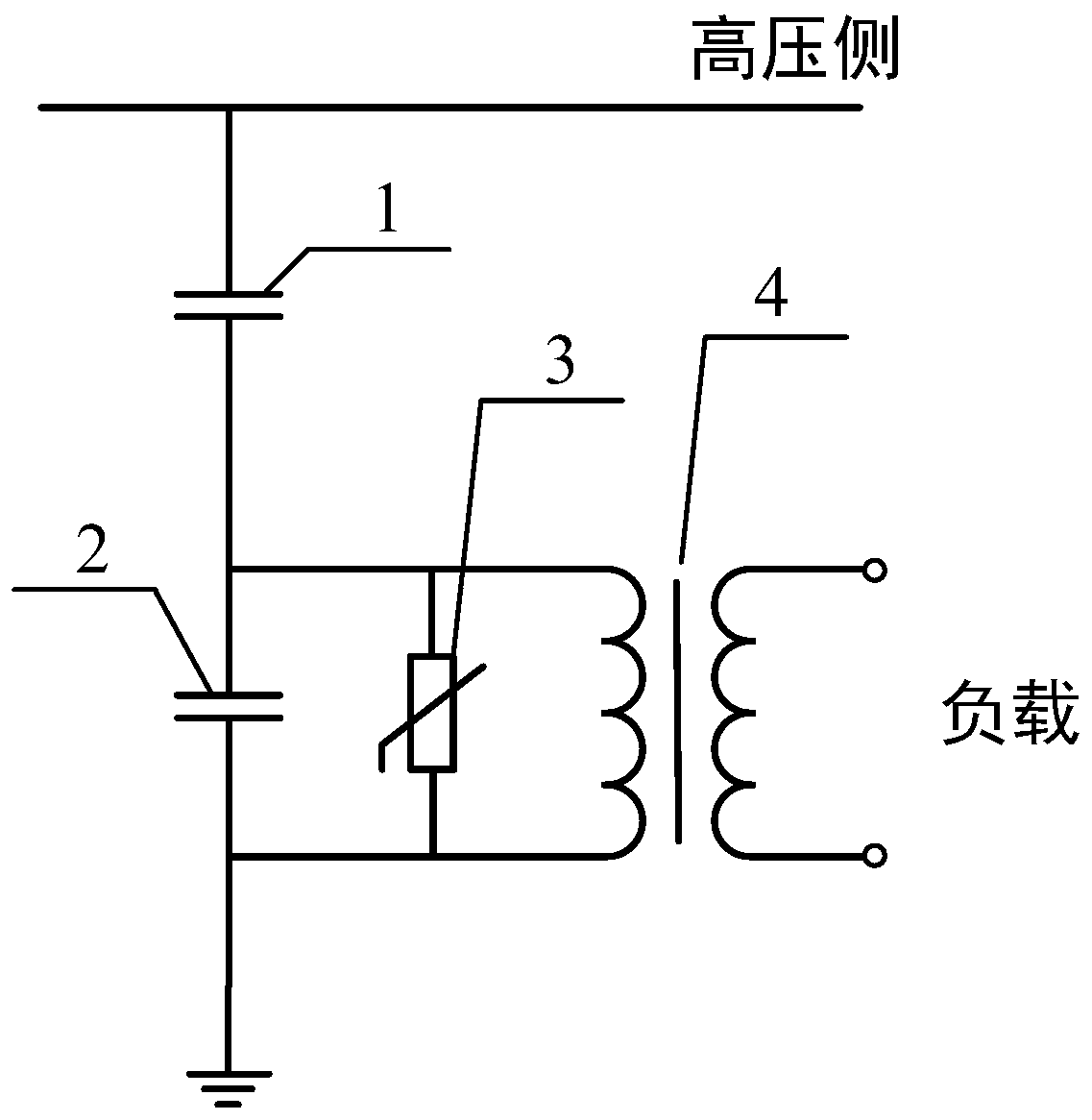
The invention discloses a reactive compensation type capacitorvoltage reduction power taking device, and the device comprises a high-voltage power taking capacitor which is used for obtaining a stable alternating current from a high-voltage side AC voltage side; a reactive compensation type capacitorvoltage reduction power taking capacitor for compensating an exciting current of a transformer; apiezoresistor for absorbing an impact current and limiting the voltage of a power taking loop; and the transformer used for increasing the alternating current, improving the power taking power and outputting the obtained alternating current. High-power and stable electric energy can be obtained at high-potential points such as a high-voltage line, various kinds of overvoltage possibly occurring on the high-voltage side can be dealt with, and power can be provided for various monitoring devices and the like.
Description
technical field [0001] The invention belongs to the technical field of power supplies, and in particular relates to a reactive power compensation capacitor step-down power-taking device. Background technique [0002] With the construction of the ubiquitous power Internet of Things, the demand for various smart terminals continues to expand. At present, 540 million smart meters and other monitoring devices in the power Internet of Things have been connected, and billions of smart terminals will be equipped in the power grid in the future. Monitoring devices such as smart terminals in the power Internet of Things are mainly used to monitor the operating status of the power system and various electrical equipment, and upload operating data to the system in real time. Both the monitoring and communication of smart terminals need to be driven by power. Based on the base number of monitoring devices such as smart terminals and the wide range of installation locations, battery powe...
Claims
Application Information
Patent Timeline
Application Date:The date an application was filed.
Publication Date:The date a patent or application was officially published.
First Publication Date:The earliest publication date of a patent with the same application number.
Issue Date:Publication date of the patent grant document.
PCT Entry Date:The Entry date of PCT National Phase.
Estimated Expiry Date:The statutory expiry date of a patent right according to the Patent Law, and it is the longest term of protection that the patent right can achieve without the termination of the patent right due to other reasons(Term extension factor has been taken into account ).
Invalid Date:Actual expiry date is based on effective date or publication date of legal transaction data of invalid patent.

