

Moving device of roller, conveying mechanism and cloth paving machine
A technology of moving devices and rollers, which is applied in the direction of transportation and packaging, spreading thin soft materials, and winding strips, etc., which can solve the problems of inconvenience and the inability of rollers to move cloth.
- Summary
- Abstract
- Description
- Claims
- Application Information
AI Technical Summary
Problems solved by technology
Method used
Image

Examples
Embodiment Construction
[0055] In order to further explain the technical solution of the present invention, the present invention will be described in detail below through specific examples.
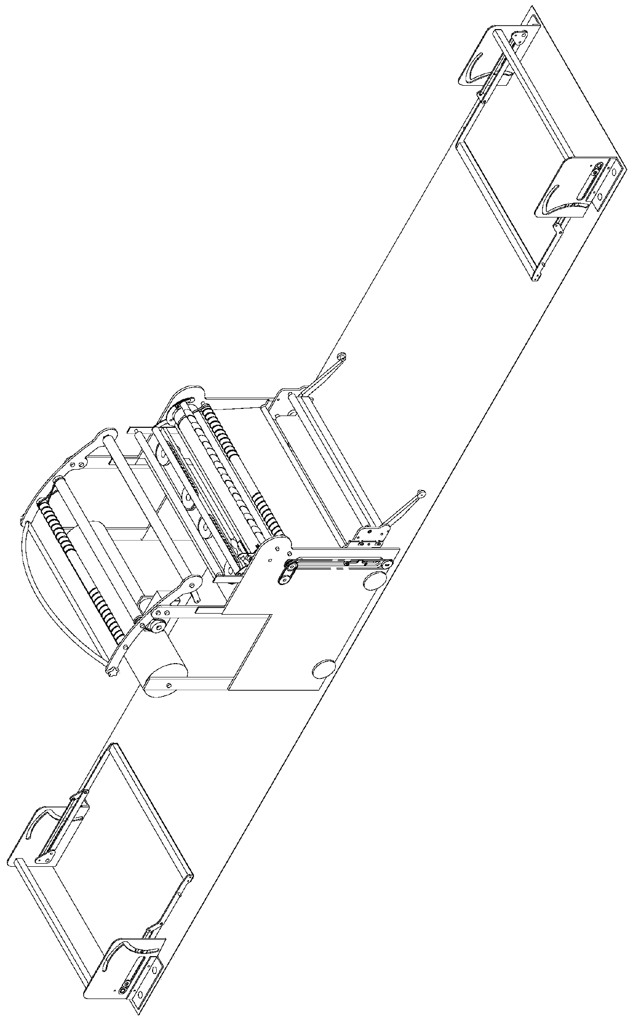
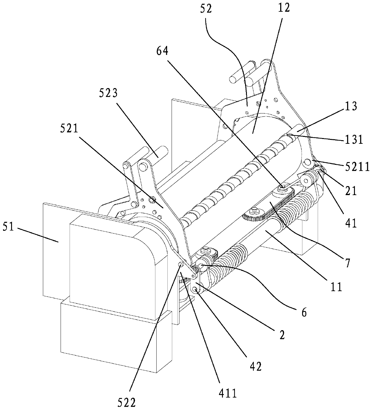
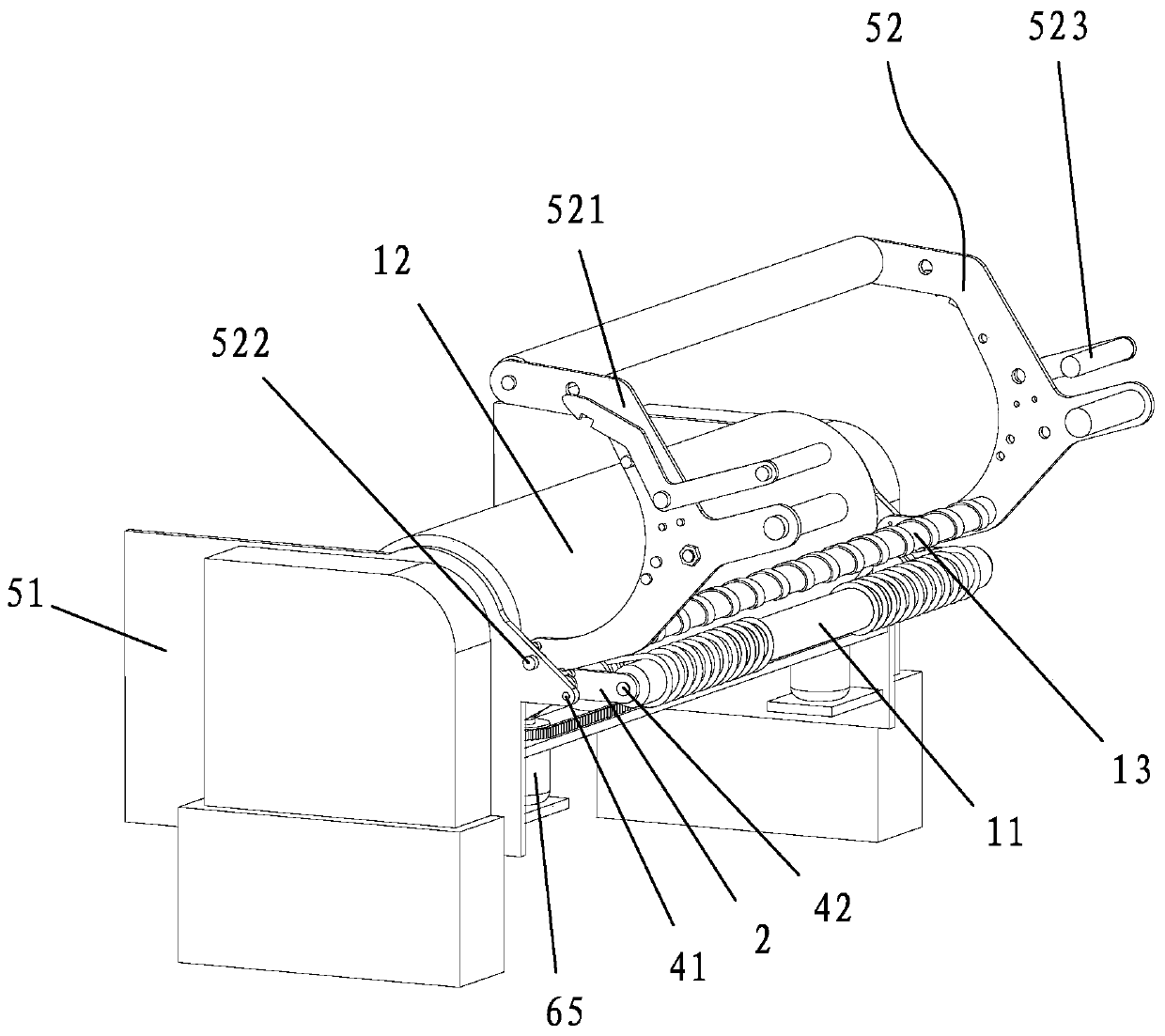
[0056] like Figure 2-6 As shown, the present invention provides a roller moving device, which includes a swing arm 2 that drives the roller roller 11 to swing, and a transmission mechanism 3 that drives the swing arm 2 to swing.
[0057] In this way, the innovation of the present invention is that the swing arm 2 and the transmission mechanism 3 are added. Before the spreading machine is loaded, the transmission mechanism 3 drives the swing arm 2 to swing, and the swing arm 2 drives the roller roller 11 to swing, so that the roller roller 11 is separated from the original position. The position of vacated larger space, so cloth just can move down smoothly under the action of gravity, and then reset roller 11 and press cloth, thereby finish upper cloth. Compared with the prior art, this case transfers the roll...
PUM
 Abstract
Description
Claims
Application Information