Assembly tool for elastic ring installation and its push rod and guide sleeve

A technology for assembling tooling and elastic rings, used in manufacturing tools, hand-held tools, etc., can solve the problems of not being too large, axial fold deformation, deflection, etc., and achieve the effect of easy production and reduced production difficulty.

Inactive Publication Date: 2016-07-06
CHINA AVIATION OPTICAL-ELECTRICAL TECH CO LTD
View PDF5 Cites 0 Cited by
  • Summary
  • Abstract
  • Description
  • Claims
  • Application Information

AI Technical Summary

Problems solved by technology

The diameter of the pushing end face on the push rod should not be too small, if it is too small, the push rod will pass through the inner hole of the elastic ring and cannot play the role of pushing the elastic ring, and the diameter of the pushing end face should not be too large, the maximum should be Do not exceed the diameter of the lower end of the tapered guide hole, because if the diameter of the push end face is too large, the push end face cannot pass through the lower end diameter of the tapered guide hole, and the elastic ring cannot be smoothly pushed into the workpiece from the tapered guide hole In the installation hole, this leads to the following problems: 1. The diameter of the push end surface must be between the inner diameter of the elastic ring installation size and the lower end hole diameter of the tapered guide hole, and because the inner diameter of the elastic ring installation size and the cone The value range between the diameters of the lower end of the tapered guide hole is very small, resulting in strict size requirements for the diameter of the push end face, which will increase the difficulty of making the push rod; 2. The movement of the elastic ring in the tapered guide hole Most of the time, the diameter of the pushing end surface is smaller than the outer diameter of the elastic ring, which results in that the pushing end surface cannot completely push the axial end surface of the elastic ring, but can only push to the radial middle or radial direction of the elastic ring. Inside, the outer side of the elastic ring is subjected to an upward friction force from the tapered guide hole, and the inner side of the elastic ring is subjected to a downward thrust from the pushing end face. If the radial dimension of the elastic ring is large and the axial dimension is small 3. Since the diameter of the push end surface is smaller than the diameter of the hole above the lower end hole of the tapered guide hole, the The push rod cannot be completely guided by the tapered guide hole, and the push rod may shake or deflect in the tapered guide hole, which will not only cause the outer edge of the push end face to scratch the wall of the tapered guide hole, but also further Increased the chance of elastic rings being pushed sideways

Method used


Image

  • Assembly tool for elastic ring installation and its push rod and guide sleeve
  • Assembly tool for elastic ring installation and its push rod and guide sleeve
  • Assembly tool for elastic ring installation and its push rod and guide sleeve

Examples


Embodiment Construction

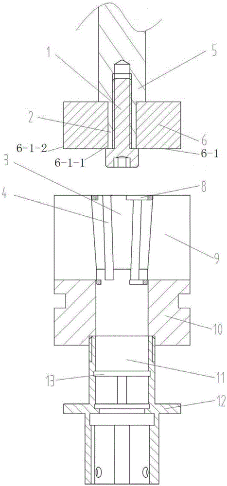
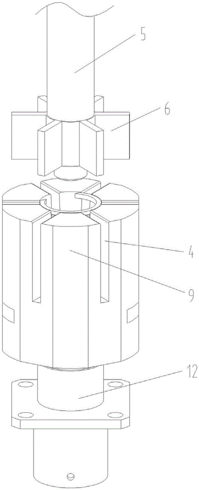
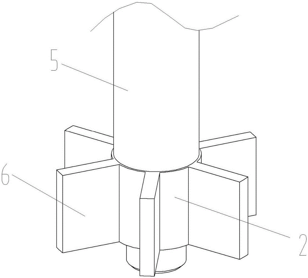
[0022] Examples of assembly tooling for elastic ring installation Figure 1~4 As shown: it includes a guide sleeve 9, a connecting sleeve 10, and a rod body 5 whose lower end is a push end. The push end of the rod body is covered with an installation sleeve 2 whose axis extends in the up and down direction, and a plurality of first sleeves are arranged at intervals around the circumference of the installation sleeve. The push block 6 with its end facing the inside of the rod body and the end extending toward the outside of the rod body. The extension direction of the head and end of the push block is the radial direction of the rod body, and the locking screw 1 whose axis extends in the vertical direction is screwed on the lower end of the rod body, and the mounting sleeve is fixedly clamped between the rod body and the locking screw. The lower end of each push block is provided with a push end face 6- which is used to straddle the upper end face of the elastic ring along the ...


PUM


Abstract

The invention relates to an assembly fixture for elastic ring installation and a push rod and a guide sleeve used by the assembly fixture. The push rod comprises a rod body of which the lower end is a pushing end; at least two pushing blocks of which the head ends extend to the direction of the inner side of the rod body and the tail ends extend to the direction of the outer side of the rod body are arranged at intervals along the circumferential direction of the pushing end of the rod body; the lower end of each pushing block is provided with an upper end face and a pushing end face, wherein the upper end face is used for crossing an elastic ring along the extension direction of the head end and the extension direction of the tail end of the corresponding pushing block when the assembly fixture is used, and the pushing end face is in pushing fit with the upper end face of the elastic ring through surface contact. The invention provides the push rod which is easy to manufacture and cannot scratch the inner hole wall of the guide sleeve.

Description

technical field [0001] The invention relates to an assembly tool for elastic ring installation, a push rod and a guide sleeve. Background technique [0002] Due to their special properties, elastic rings (such as circlips, retaining rings, etc.) need special assembly tooling to ensure the smooth progress of the installation process when they are assembled into the mounting holes of the corresponding workpieces. Existing assembly tooling for installing elastic rings is disclosed in Chinese patent CN201544194U "A device for installing a circlip for a hole". The device includes a guide sleeve and a push rod. Small tapered pilot hole, the diameter of the lower port of the tapered pilot hole is the same as the diameter of the mounting hole of the workpiece. The lower end of the push rod is provided with a push end face for pushing and matching with the elastic ring, and the diameter of the push end face is smaller than the diameter of the tapered guide hole and larger than the i...

Claims


Application Information

Patent Timeline
Patent Type & Authority Patents(China)
IPC IPC(8): B25B27/02
CPCB25B27/28
Inventor 魏宝张军昌陈玉成王文涛周凡陈明山
Owner CHINA AVIATION OPTICAL-ELECTRICAL TECH CO LTD
Why Eureka
Try Eureka