Digital microfluidic droplet driving device and method

A digital microfluidic and driving device technology, applied in the direction of fluid controllers, chemical instruments and methods, laboratory appliances, etc., can solve the difficulty of making digital microfluidic droplet driving devices and limit the large-scale flexibility of digital droplets Thread control and other issues

Active Publication Date: 2018-03-06
深圳市芯卫来科技有限公司
View PDF7 Cites 47 Cited by
  • Summary
  • Abstract
  • Description
  • Claims
  • Application Information

AI Technical Summary

Problems solved by technology

Obviously, in the existing digital microfluidic droplet driving device, the more the number of driving electrode blocks, the more the number of matching signal lines, and the more difficult it is to manufacture the digital microfluidic droplet driving device. This will greatly limit the full use of advantages such as large-scale flexible multi-threaded control of digital droplets

Method used


Image

  • Digital microfluidic droplet driving device and method
  • Digital microfluidic droplet driving device and method
  • Digital microfluidic droplet driving device and method

Examples


Embodiment 1

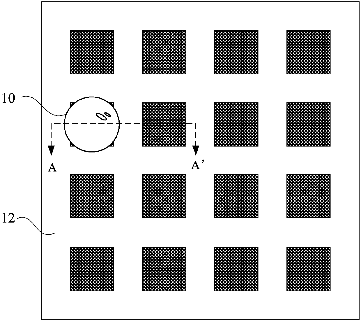
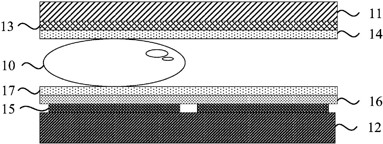
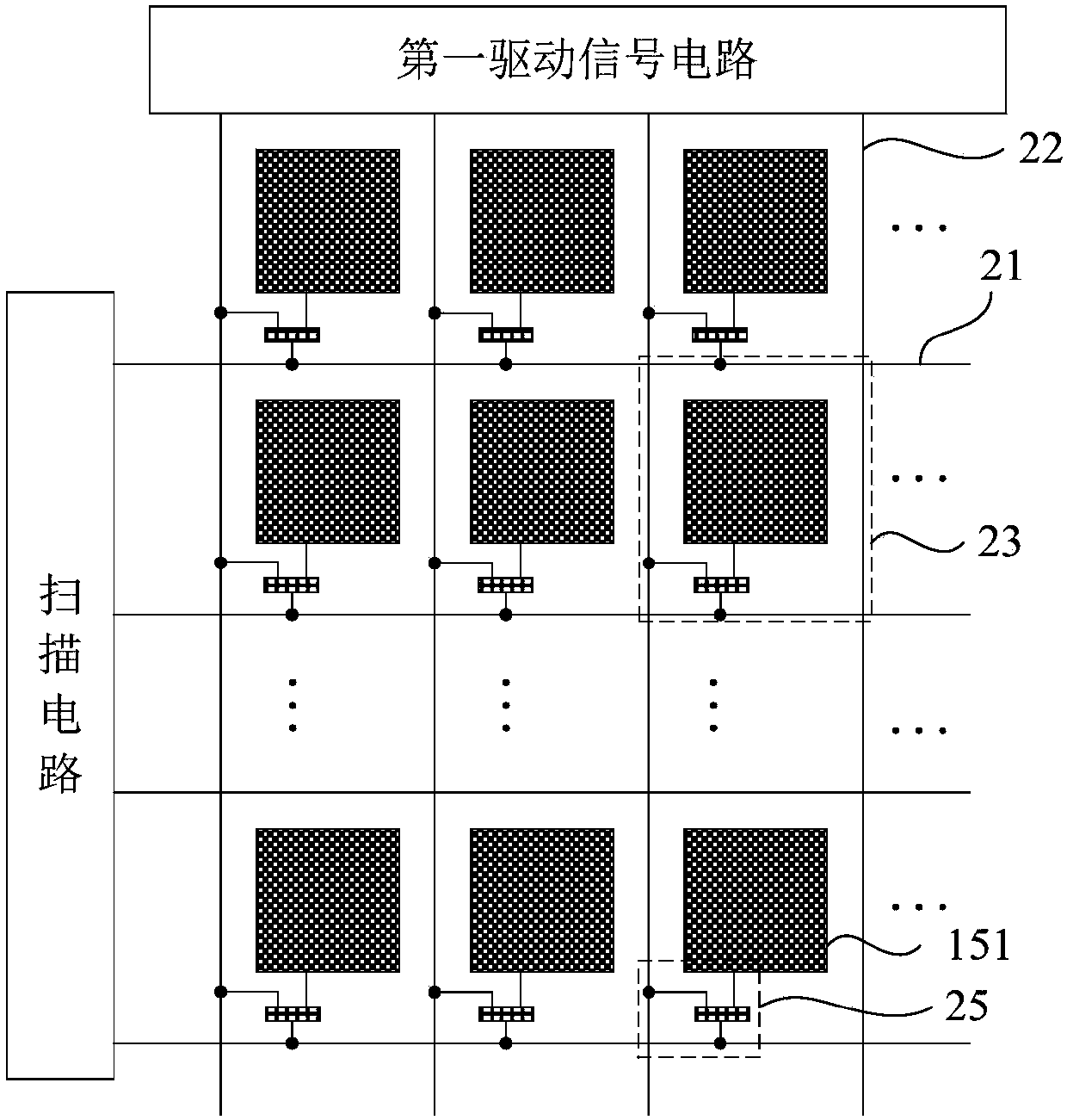
[0046] figure 1 It is a schematic top view structural diagram of a digital microfluidic droplet driving device provided in Embodiment 1 of the present invention, figure 2 is along figure 1 Schematic diagram of the cross-sectional structure of the middle section line A-A', image 3 yesfigure 1 Schematic diagram of the structure of the control circuit layer in the digital microfluidic droplet driving device, Figure 4 yes image 3 Schematic diagram of the control switch. refer to figure 1 , figure 2 , image 3 with Figure 4 , the digital microfluidic droplet driving device specifically includes a first substrate 11, a second substrate 12 ( figure 1 Only the second substrate 12) and the control circuit layer are shown in , and the accommodation space for the droplet 10 is formed between the first substrate 11 and the second substrate 12. Wherein, a reference electrode layer 13 is provided on a side of the first substrate 11 close to the second substrate 12 , and a fir...

Embodiment 2

[0064] Figure 7 It is a circuit diagram of another digital microfluidic droplet driving device provided in Embodiment 2 of the present invention; Figure 8 yes Figure 7 The equivalent circuit diagram of the transistor in the off and on states. Compared with Embodiment 1, in this embodiment, the digital microfluidic droplet driving device further includes a second driving signal line 31 and a third driving signal line 41 . Specifically, see Figure 7 with Figure 8 , the second driving signal line 31 is electrically connected to the reference electrode; the third driving signal line 41 is electrically connected to the driving electrode block.

[0065] Combine below Figure 7 with Figure 8 The driving method of the digital microfluidic droplet driving device provided in this embodiment will be described in detail. The droplet driving method of the digital microfluidic droplet driving device includes:

[0066] S110. After the droplet is dropped into the digital microfl...

Embodiment 3

[0075] Figure 9 It is a schematic cross-sectional view of the digital microfluidic droplet driving device provided in Embodiment 3 of the present invention, Figure 10 It is a circuit diagram of another digital microfluidic droplet driving device provided in Embodiment 3 of the present invention. see Figure 9 with Figure 10 , the digital microfluidic droplet driving device also includes a third substrate 18 opposite to the second substrate 12; the second substrate 12 is located between the first substrate 11 and the third substrate 18; the third substrate 18 includes a The first surface of the substrate 12 and a plurality of connection pins 181; the control circuit layer is integrated on the third substrate 18, the connection pins 181 are located in the first surface of the third substrate 18, and are electrically connected to the output end of the control switch, The connecting pins 181 are arranged in one-to-one correspondence with the driving electrode blocks on the s...


PUM


Abstract

The invention discloses a digital microfluidic droplet driving device and method. The digital microfluidic droplet driving device comprises a first substrate, a second substrate and a control circuitlayer. A droplet accommodating space is formed between the first substrate and the second substrate. A reference electrode is arranged in one side of the first substrate. A first hydrophobic layer isarranged in one side of the reference electrode layer. A driving electrode layer is arranged in one side of the second substrate. The driving electrode layer comprises multiple driving electrode blocks spaced apart from each other. A dielectric layer is disposed on one side of the driving electrode layer. A second hydrophobic layer is arranged in one side of the dielectric layer. The control circuit layer comprises a scanning line and a first driving signal line. The scanning line and the first driving signal line intersect to define a plurality of control units. The control units are arrangedcorresponding to the driving electrode blocks. The digital microfluidic droplet driving device can greatly improve the number of independent electrodes in the microfluidic chip and a controllable droplet size and realize free movement, separation and merging of high-density droplets.

Description

technical field [0001] Embodiments of the present invention relate to digital droplet microfluidic technology, and in particular to a digital microfluidic droplet driving device and a driving method. Background technique [0002] With the development of modern biomedical engineering technology, microfluidic chip and lab-on-a-chip technology are getting more and more attention. [0003] Due to the flexibility, ease of use, and reusability of microfluidic chips, they can provide powerful sample pretreatment capabilities in biomedical research and applications such as genomics, proteomics, and precision medicine. The basic feature and greatest advantage of microfluidic chips are the flexible combination and large-scale integration of various unit technologies on a small and controllable platform, which can control the reagents on the microchip to perform automatic sampling, dilution, reagent addition, separation and other operations to realize microchip laboratory functions. ...

Claims


Application Information

Patent Timeline
Patent Type & Authority Applications(China)
IPC IPC(8): B01L3/00
CPCB01L3/50273B01L3/502784B01L2300/0887B01L2400/0424B01L2400/0427
Inventor 程鑫行亚茹刘显明刘羽陈日飞
Owner 深圳市芯卫来科技有限公司
Why Eureka
Try Eureka