Reducing angular dependency in microcavity color OLEDs

a color oled, microcavity technology, applied in the direction of incadescent envelope/vessel, discharge tube luminescnet screen, organic semiconductor device, etc., can solve the problem of undesirable dependence of color emitted by microcavity oled, and achieve the effect of reducing the angular dependence of light, improving the viewing angle of microcavity oled device, and reducing manufacturing difficulty

Active Publication Date: 2006-10-05
GLOBAL OLED TECH
View PDF2 Cites 46 Cited by
  • Summary
  • Abstract
  • Description
  • Claims
  • Application Information

AI Technical Summary

Benefits of technology

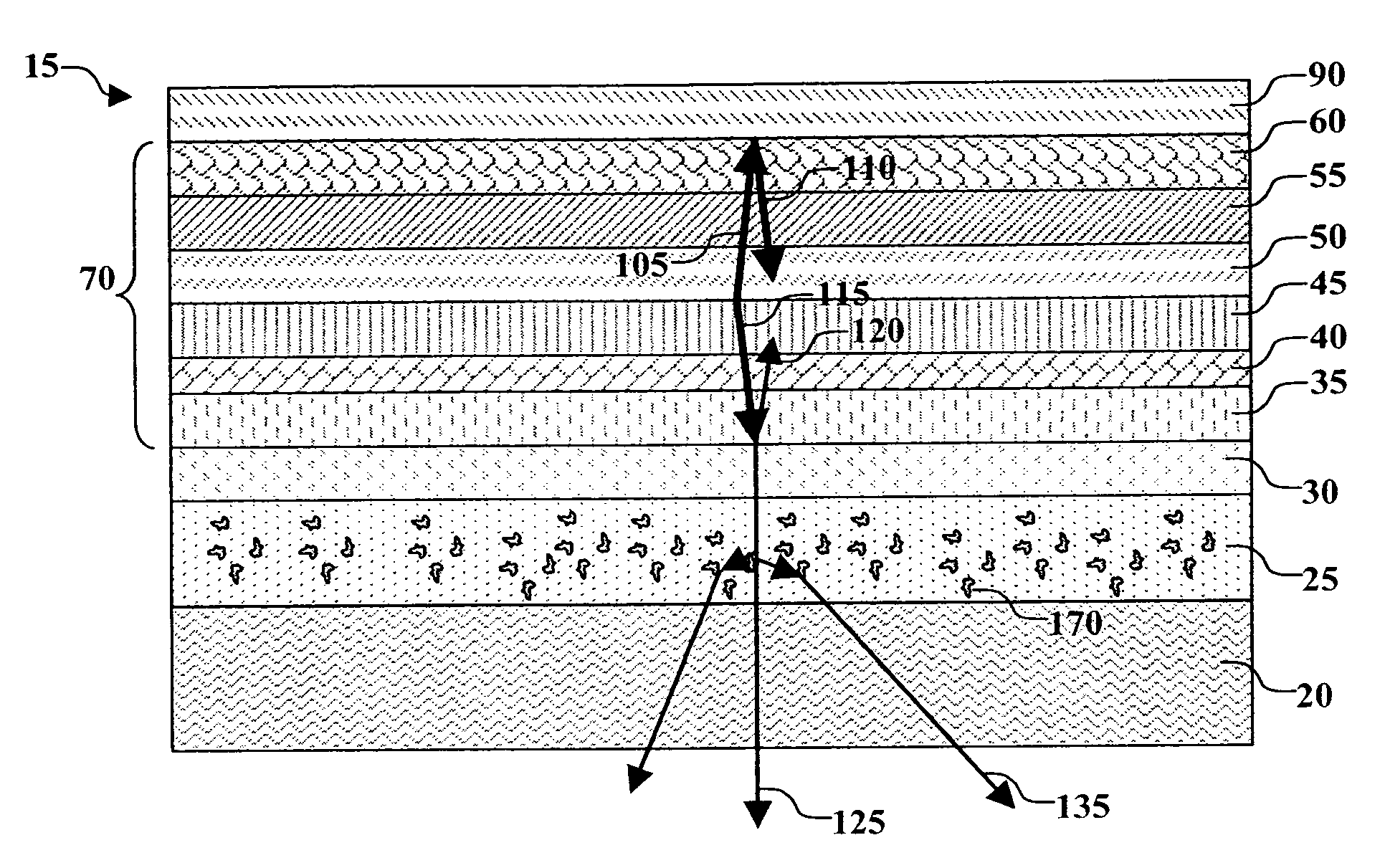
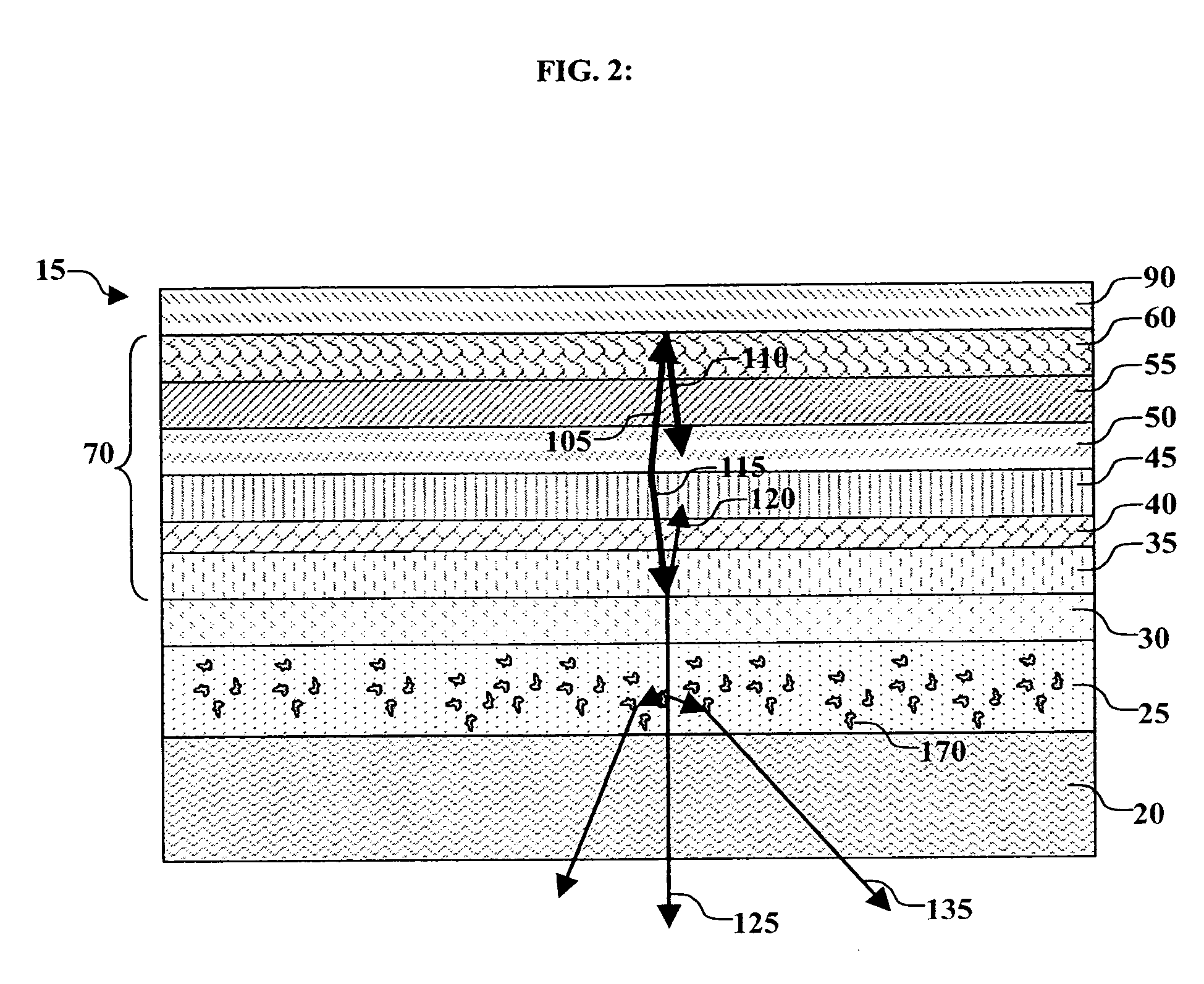
[0008] c) a color filter element disposed over the microcavity structure including a light scattering material selected so as to reduce the angular dependence of the light that has passed through the color filter element.
[0009] It is an advantage of this invention that it can improve the viewing angle of a microcavity OLED device. It is a further advantage of this invention that this improvement can be achieved without the need for a separate light-scattering layer, thereby reducing the manufacturing difficulty.

Problems solved by technology

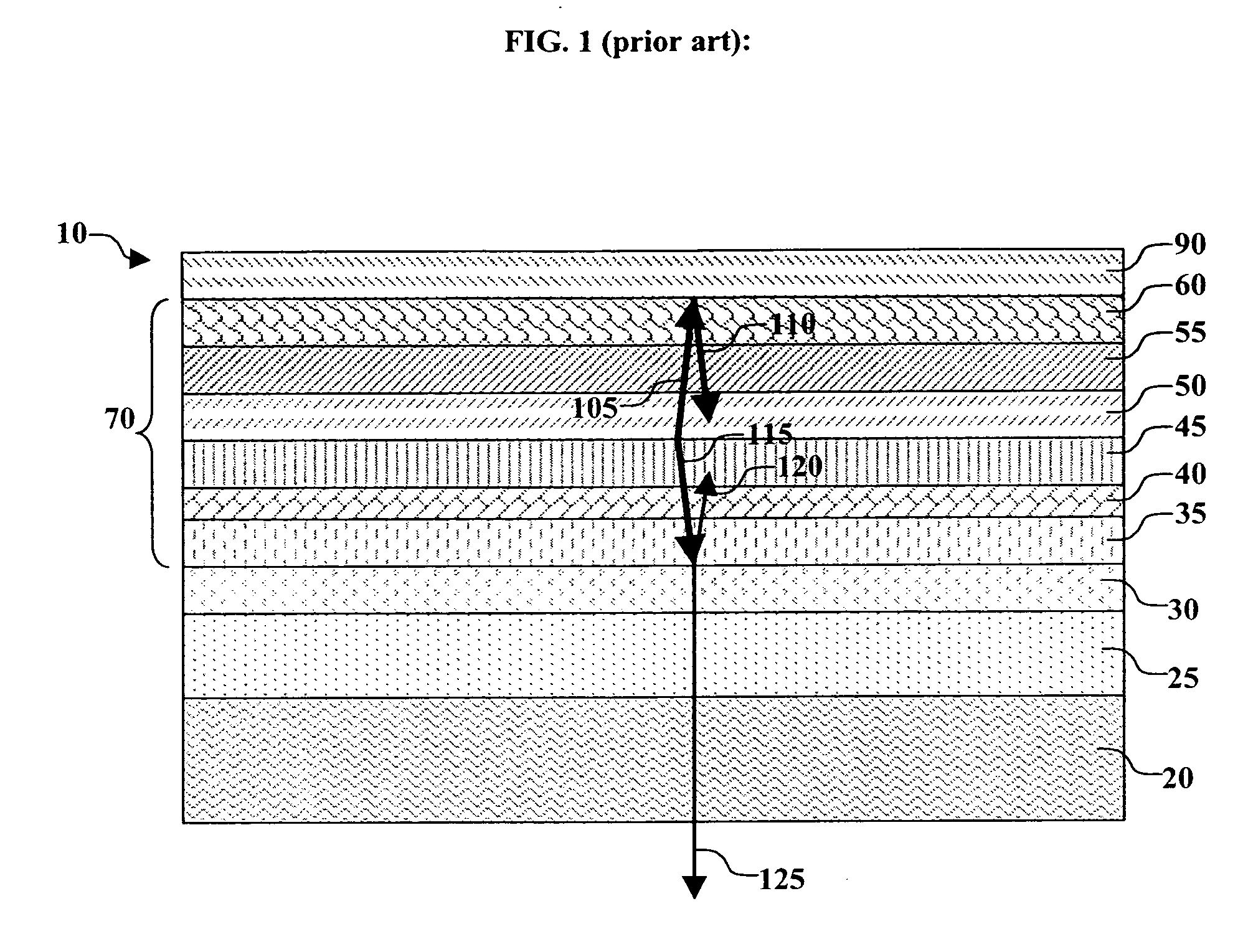
However, the resonant wavelength of a microcavity is also a function of angle and thus the color emitted by a microcavity OLED tends to have an undesirable dependence on angle, generally shifting toward the shorter wavelengths as the viewing angle shifts from normal to more oblique angles.

Method used


Image

  • Reducing angular dependency in microcavity color OLEDs
  • Reducing angular dependency in microcavity color OLEDs
  • Reducing angular dependency in microcavity color OLEDs

Examples


Embodiment Construction

[0018] The term “OLED device” or “organic light-emitting display” is used in its art-recognized meaning of a display device comprising organic light-emitting diodes as pixels. A color OLED device emits light of at least one color. The term “multicolor” is employed to describe a display panel that is capable of emitting light of a different hue in different areas. In particular, it is employed to describe a display panel that is capable of displaying images of different colors. These areas are not necessarily contiguous. The term “full color” is commonly employed to describe multicolor display panels that are capable of emitting in the red, green, and blue regions of the visible spectrum and displaying images in any combination of hues. The red, green, and blue colors constitute the three primary colors from which all other colors can be generated by appropriate mixing. However, the use of additional colors to extend the color gamut of the device is possible. The term “hue” refers to...


PUM


Abstract

A microcavity color OLED device, includes at least one light-emitting layer arranged so as to produce light; a reflector and a semi-transparent reflector forming a microcavity structure for resonating the light produced in the at least one light emitting layer; and a color filter element disposed over the microcavity structure including a light-scattering material selected so as to reduce the angular dependence of the light that has passed through the color filter element.

Description

FIELD OF THE INVENTION [0001] The present invention relates to organic electroluminescent (EL) devices. More specifically, this invention relates to an emitting EL device with improved viewing angle. BACKGROUND OF THE INVENTION [0002] Full color organic electroluminescent (EL) devices, also known as organic light-emitting diode (OLED) devices, have been demonstrated as a new type of flat panel display. OLED devices are attractive because of their low driving voltage, high luminance, wide-angle viewing and capability for full-color flat emission displays. In its simplest form, an organic EL device is comprised of an anode for hole injection, a cathode for electron injection, and an organic EL medium sandwiched between these electrodes to support charge recombination that yields emission of light. An example of an organic EL device is described in commonly-assigned U.S. Pat. No. 4,356,429. Other examples have been described by Tang et al. in U.S. Pat. 4,769,292 and 4,885,211. In order...

Claims


Application Information

Patent Timeline
Patent Type & Authority Applications(United States)
IPC IPC(8): H01J1/62
CPCB82Y20/00B82Y30/00H01L27/3211H01L2251/5369H01L51/5265H01L51/5268H01L27/322H10K59/35H10K50/125H10K50/852H10K50/854H10K2102/331
Inventor GHOSH, AMALKUMAR P.CARMODY, MICHAEL J.SHORE, JOEL D.
Owner GLOBAL OLED TECH
Why Eureka
Try Eureka