2d/3d switch liquid crystal display panel and 2d/3d selection liquid crystal display

a liquid crystal display panel and switching type technology, applied in optics, instruments, electrical equipment, etc., can solve the problems of particularly serious problems, easy breakage of terminal formation parts by external stress,

Inactive Publication Date: 2005-12-29
SHARP KK
View PDF11 Cites 61 Cited by
  • Summary
  • Abstract
  • Description
  • Claims
  • Application Information

AI Technical Summary

Benefits of technology

[0019] With the arrangement, the active areas of the parallax barrier means and the switching means are wider than the active area of the display image generating means. In this case, it is possible to restrain such a problem that other areas outside the active areas of the parallax barrier means and the switching means shield off the light having passed through a vicinity of an end portion of the display screen and through the active area of the display image generating means. This improves the viewing angle during 2D display.
[0024] The arrangement shortens the distance between the display image generating means and the patterned retardation plate. This makes it easier to obtain the 3D display effect during 3D display.
[0026] With the arrangement, the light having passing through the switching means enters the patterned retardation plate of the parallax barrier, and then enters the parallax barrier polarizer. The light beams entering the patterned retardation plate are subjected to different optical modulations in the respective optical areas of the patterned retardation plate, and become light beams having different polarization states. During 2D display, the parallax barrier polarizer renders the same transmittance to the light having passed through the optical areas. This deactivates the effect of the parallax barrier means. In contrast, during the 3D display, the parallax barrier polarizer renders different transmittances to the light beams; i.e., to (i) the light having passed through one optical area serving as a transmitting area and to (ii) the light having passed through the other optical area serving as a shielding area, respectively. This activates the effect of the parallax barrier means.
[0029] With the arrangement, the terminal formation portions of the display liquid crystal panel and the switching liquid crystal panel overlap with each other when viewed from the display screen. This improves strength against a stress exerted on the display screen, and makes it difficult to generate a crack in the substrate having the terminal formation portions.
[0031] With the arrangement, the terminal formation portions of the display liquid crystal panel and the switching liquid crystal panel overlap with each other when viewing from the display screen. This improves strength against a stress exerted on the display screen, and makes it difficult to generate a crack in the substrate having the terminal formation portions.
[0033] The arrangement shorten distance between the substrate having the terminal formation portion of the display liquid crystal panel and the substrate having the terminal formation portion of the switching liquid crystal panel. On this account, when an external force is exerted on the terminal formation portions, the substrates make contact with each other, thereby improving strength of the substrate. This makes it difficult to generate a crack in the substrates having the terminal formation portion.

Problems solved by technology

However, the following problems arise in the conventional 2D / 3D switching liquid crystal display devices.
Therefore, even when the observer obliquely views the display screen of the 2D / 3D switching type liquid crystal display device from a point within the viewing angle secured by the display liquid crystal layer, the other components (i.e., the switching liquid crystal panel and the parallax barrier) possibly prevent recognition of an image displayed on a peripheral portion of a display area of the display liquid crystal layer.
Because the terminal formation portions thus protrude from the 2D / 3D switching type liquid crystal display panel, and are portions of the substrates made of glass, the terminal formation portions tend to be easily broken by external stress.
Such a problem is particularly serious for liquid crystal display panels for a mobile phone and a PDA (Personal Digital Assistants).

Method used


Image

  • 2d/3d switch liquid crystal display panel and 2d/3d selection liquid crystal display
  • 2d/3d switch liquid crystal display panel and 2d/3d selection liquid crystal display
  • 2d/3d switch liquid crystal display panel and 2d/3d selection liquid crystal display

Examples


Embodiment Construction

[0053] Hereinafter, detail of the present invention is further described in accordance with examples and comparative examples; however, the present invention is not limited to these.

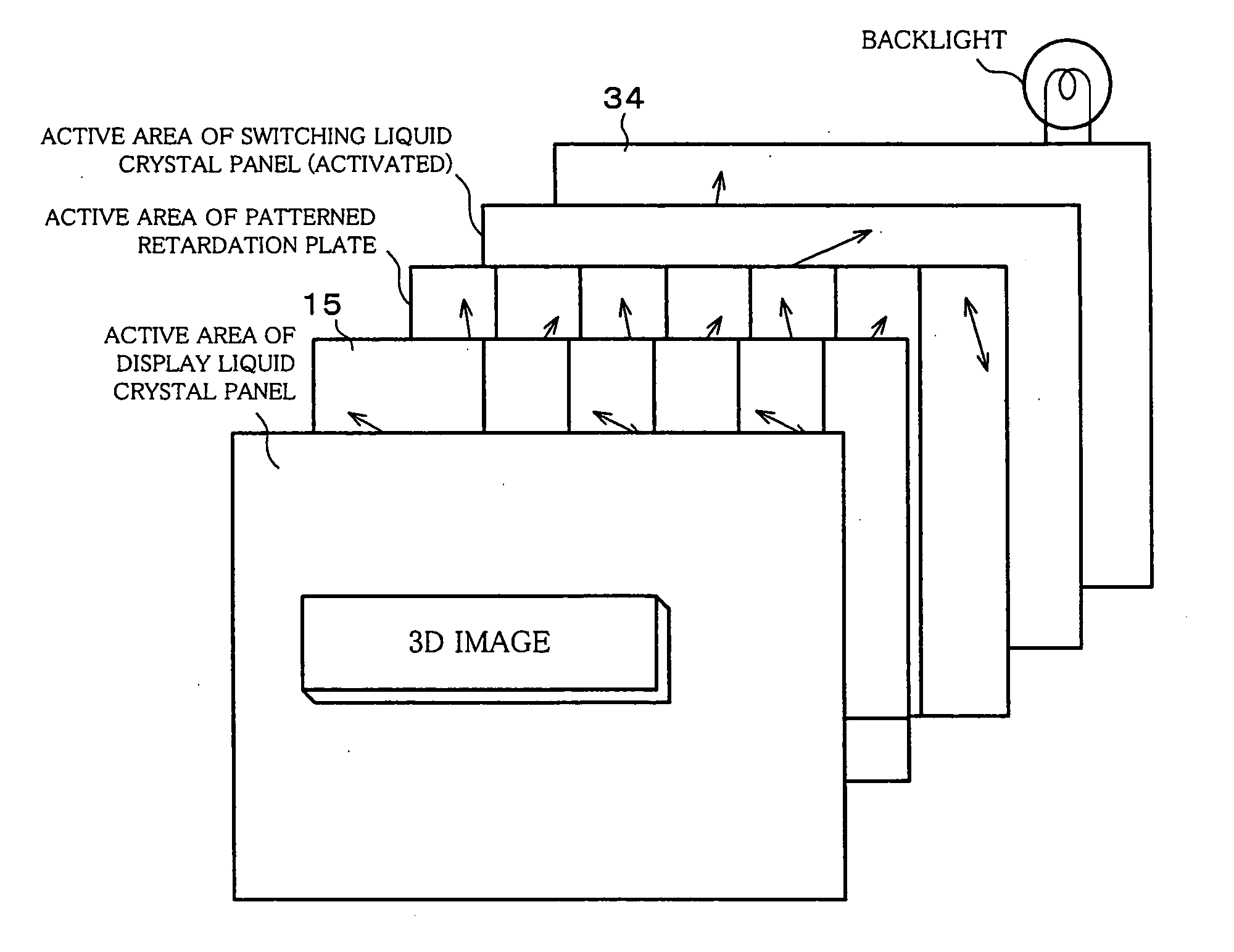
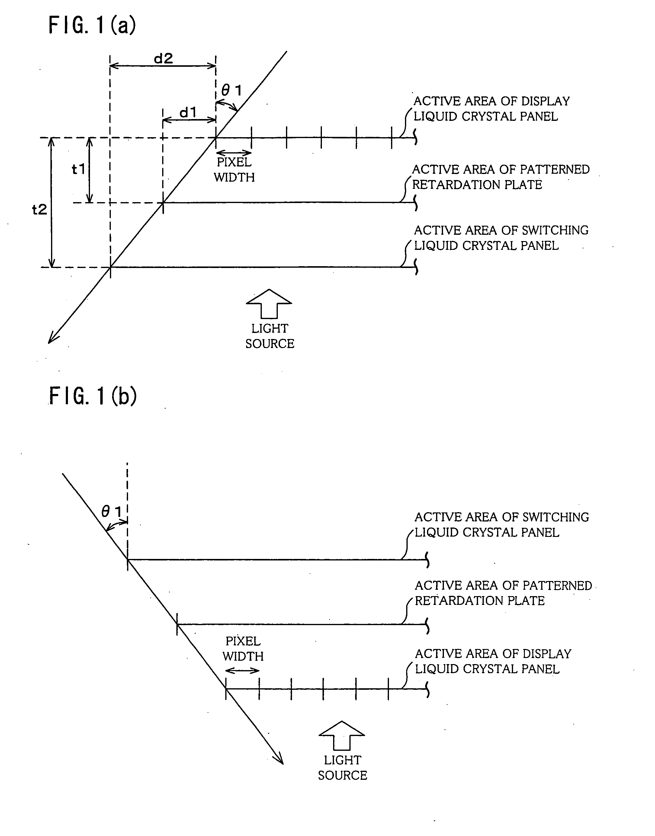
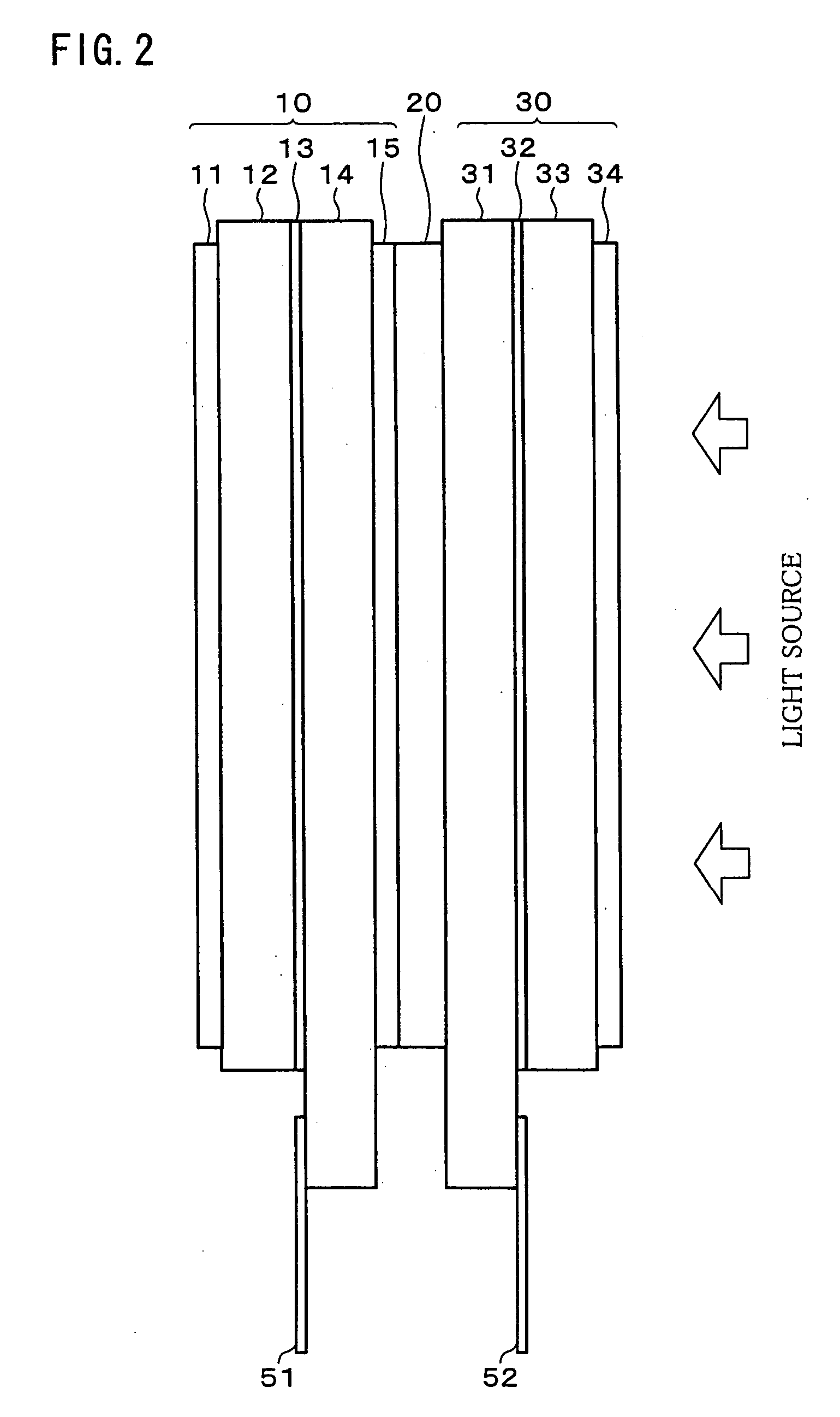
[0054] The following description deals with an embodiment of the present invention with reference to FIG. 1 through FIG. 10 and FIG. 12 through FIG. 14. Firstly, schematically explained is a structure of a 2D / 3D switching type liquid crystal display panel according to the present invention with reference to FIG. 2.

[0055] As shown in FIG. 2, the 2D / 3D switching type liquid crystal display panel is constructed by assembling a display liquid crystal panel 10, a patterned retardation plate 20, and a switching liquid crystal panel 30. Further, the 2D / 3D switching type liquid crystal display device is provided by providing a driving circuit and a backlight (light source) in the 2D / 3D switching type liquid crystal display panel according to the present invention.

[0056] The display liquid crystal panel 10 is ...


PUM

PropertyMeasurementUnit
heightaaaaaaaaaa
heightaaaaaaaaaa
distanceaaaaaaaaaa

Abstract

A 2D / 3D switching type liquid crystal display device includes: (i) display liquid crystal panel (10) for generating an image in accordance with input image data; (ii) patterned retardation plate (20) for rendering a certain viewing angle to a display image during 3D display, so as to provide a 3D effect; and (iii) a switching liquid crystal panel (30) for switching 2D display and 3D display by activating and deactivating the effect of the parallax barrier means. The patterned retardation plate (20) and the switching liquid crystal panel (30) respectively have wider active areas than an active area of the display image generating means. With this, the 2D / 3D switching liquid crystal display device allows for a viewing angle in 2D as wide as a viewing angle of 2D-only display.

Description

TECHNICAL FIELD [0001] The present invention relates to a 2D / 3D switching type liquid crystal display panel, and to a 2D / 3D switching type liquid crystal display device, both of which allow switching of a first display (2D display) and a second display (3D display). BACKGROUND ART [0002] In a normal field of vision, the two eyes perceive views of the world from two different perspectives due to their spatial separation within the head. The images from these two perspectives are then recognized as a stereoscopic image by the brain due to parallax of the two images. By utilizing this principle, there has been developed a liquid crystal display in which 3D (three-dimensional) display is carried out by parallax generated by causing an observer to see images from two different points of view through the right eye and the left eye, respectively. [0003] In some 3D liquid crystal displays, images from different points of view are supplied to the respective eyes of the observer by first enco...

Claims


Application Information

Patent Timeline
Patent Type & Authority Applications(United States)
IPC IPC(8): G02B30/25G02F1/13G02F1/1335G02F1/13363G02F1/1345G02F1/1347H04N13/00H04N13/04
CPCG02F1/13363H04N13/0454H04N13/0409G02F2413/09H04N13/31H04N13/359G02F1/133631G02F1/1335G02F1/1333G02F1/13
Inventor KOYAMA, YOSHIHIDEMIYAZAKI, SHINICHI
Owner SHARP KK
Why Eureka
Try Eureka