Image display

a technology of image display and display screen, applied in the direction of identification means, instruments, optics, etc., can solve the problems of inability to achieve wide viewing angle and extremely dark imag

Inactive Publication Date: 2006-08-31
SOPHIA CO LTD +2
View PDF4 Cites 67 Cited by
  • Summary
  • Abstract
  • Description
  • Claims
  • Application Information

AI Technical Summary

Benefits of technology

[0016] According to the second aspect of the invention, since the one or a plurality of auxiliary light sources are turned on by the light source control means after switching the three-dimensional image the two-dimensional image, generation of cross-talk in the three-dimensional image is avoided by preventing the left-eye image and the right-eye image from reaching the both eyes by the one or a plurality of auxiliary light sources which widens the viewing angle, and switching from the three-dimensional image to the two-dimensional image is achieved without giving a feeling of discomfort to the viewer.
[0017] According to the third aspect of the invention, since switching to the three-dimensional image is performed after the one or a plurality of auxiliary light sources are turned off, both of the left-eye image and the right-eye image reach both eyes by illuminating the one or a plurality of auxiliary light sources. Therefore, by switching to the three-dimensional image after causing the light from the backlight to reach the both eyes of the viewer by turning off the one or a plurality of auxiliary light sources, generation of the cross-talk in the left-eye image and the right-eye image is reliably prevented, and hence switching from the image for two-dimensional display to the image for three-dimensional display can be performed smoothly without giving a sense of discomfort to the viewer.
[0018] According to the fourth aspect of the invention, since the backlight is turned off or dimmed when turning on the auxiliary light source, durability of the device can be improved by controlling heat generation of the light source and promotion of energy saving is achieved by controlling power consumption.
[0019] According to the fifth aspect of the invention, since the backlight is also turned on when turning on the auxiliary light source, the angle of visibility when displaying the image for two-dimensional display can be enlarged by increasing the light amount transmitting through the liquid crystal display panel.
[0020] According to the sixth aspect of the invention, since the auxiliary light source is higher in brightness than the backlight, the angle of visibility when displaying the image for two-dimensional display can be enlarged.
[0021] According to the seventh aspect of the invention, since the backlight is disposed between the liquid crystal display panel and the auxiliary light source, the lights for the left eye and for the right eye can be incident into the liquid crystal display panel without being intercepted by the auxiliary light source.

Problems solved by technology

Therefore, those who are not in the viewing angle cannot see the image, or the image appears to be extremely dark.
In such an image display system, there is a problem that a wide viewing angle cannot be achieved due to the structure of an optical system thereof, when a demonstrative display for collecting people in front of the image display system is desired for people viewing from points other than a predetermined viewing zone set in front of the image display system, which may pose an impediment when appealing characteristics of the image display system.

Method used


Image

  • Image display
  • Image display
  • Image display

Examples


Embodiment Construction

[0029] Referring now to the drawings, an embodiment of the present invention will be described.

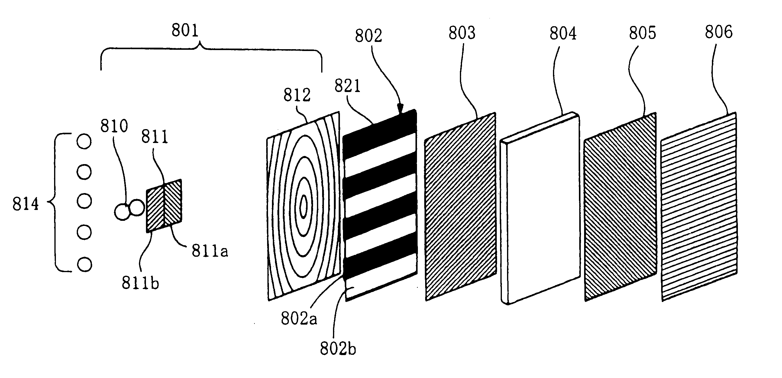
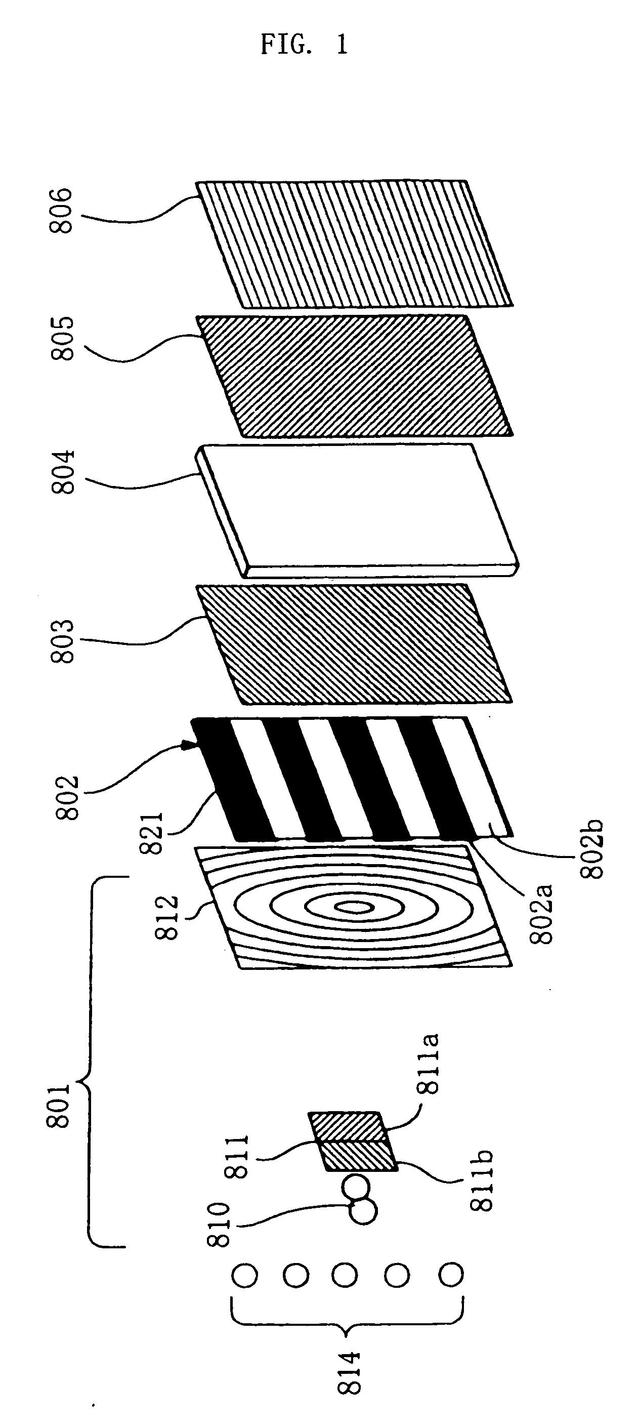
[0030]FIG. 1 is an exploded perspective view showing an optical system of an image display system according to an embodiment of the present invention.

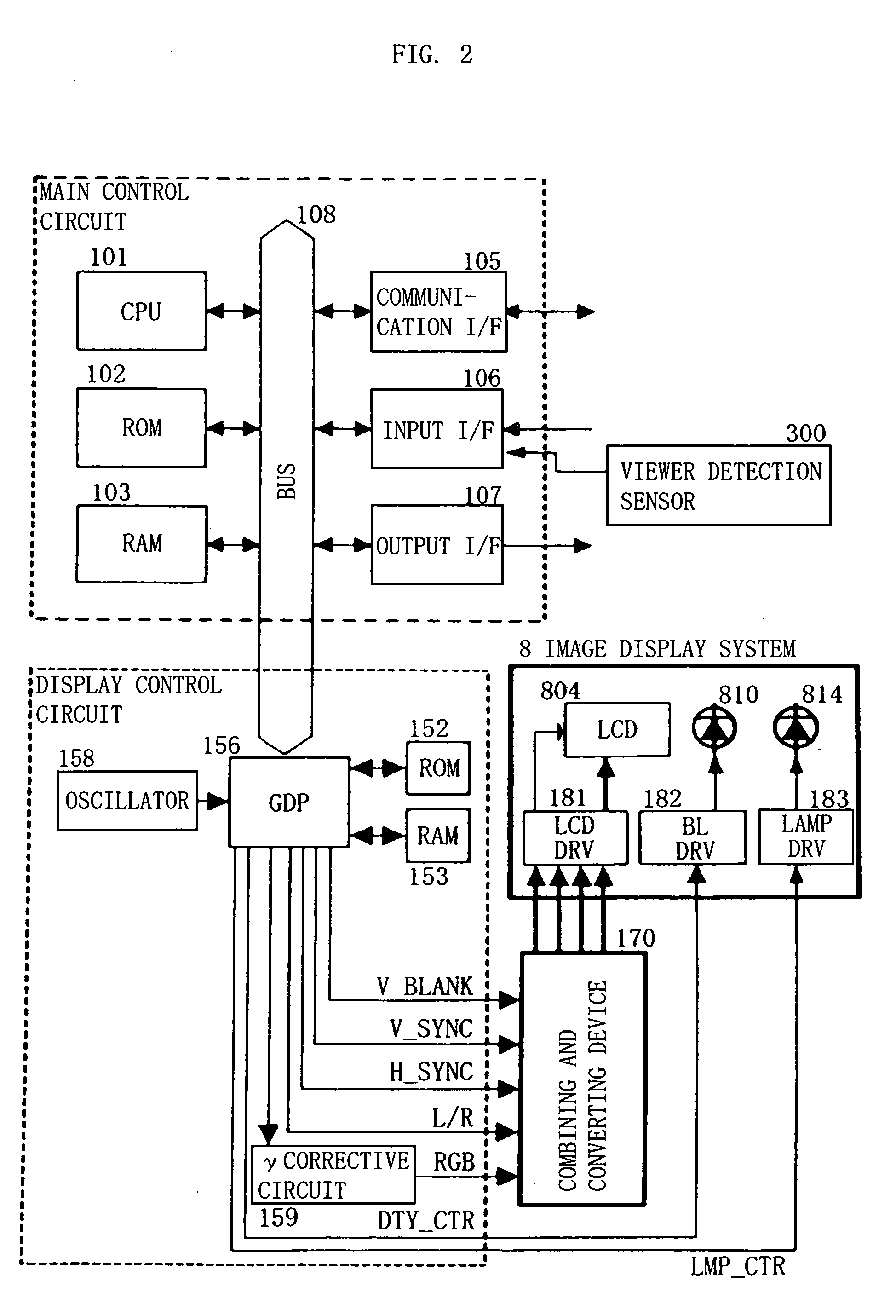
[0031]FIG. 2 is a block diagram showing a control system of the same.

[0032]FIG. 3 is a plan view of the optical system of the same.

[0033]FIG. 4 is a flowchart showing an example of light source control.

[0034]FIG. 5 is an exploded perspective view showing the optical system of the image display system according to another embodiment.

BEST MODE FOR CARRYING OUT THE INVENTION

[0035] Referring now to the drawings, an embodiment of the present invention will be described.

[0036]FIG. 1 shows an example of an image display system 8 to which the present invention is applied, and a light source 801 (main light source) includes a light emitting device 810, a polarizing filter 811, and a Fresnel lens 812.

[0037] The light emitting device (backlight...


PUM


Abstract

The present invention provides an image display system in which an image can be seen from positions other than predetermined viewing position. The image display system includes optical means for allowing light from a backlight (810) to be transmitted to a left eye image area and a right eye image area and causing the transmitted lights from the respective image areas to enter into a left eye and a right eye of an viewer independently, and image parallax switching means for selectively displaying an image for three-dimensional display which causes parallax between both eyes of the viewer when displaying a three-dimensional image to the viewer or an image for two-dimensional display which does not cause parallax between the both eyes of the viewer when displaying a two-dimensional image to the viewer on the display area, auxiliary light sources (814) for irradiating a liquid crystal display panel (804) and causing the irradiated light to be transmitted through the left eye image area or the right eye image area and enter into the both eyes of the viewer and light source control means which turns on the backlight (810) when showing the three-dimensional image to the viewer and turns on the auxiliary light sources (814) when showing the two-dimensional image to the viewer are provided.

Description

TECHNICAL FIELD [0001] The present invention relates to an image display system which can display an a three-dimensional image. BACKGROUND ART [0002] Hitherto, an image display system for displaying a stereoscopic image (three-dimensional image) by displaying an right-eye image and a left-eye image having parallax using a liquid crystal display unit or the like is known (JP-A-10-63199, etc.). [0003] [Patent Document 1] JP-A-10-63199 [0004] However, in the related art, since it is intended only to show the three-dimensional image to a viewer, the viewing angle is set to a small angle. Therefore, those who are not in the viewing angle cannot see the image, or the image appears to be extremely dark. In such an image display system, there is a problem that a wide viewing angle cannot be achieved due to the structure of an optical system thereof, when a demonstrative display for collecting people in front of the image display system is desired for people viewing from points other than a ...

Claims


Application Information

Patent Timeline
Patent Type & Authority Applications(United States)
IPC IPC(8): G09G3/36G02B27/22G02B30/25G09G3/34H04N13/00H04N13/04
CPCG09G3/003G09G3/3611H04N13/0409H04N13/0418H04N13/31H04N13/32G02F1/13G09F9/30
Inventor IOKI, SADAOARISAWA, SANJITOMITA, SEIJIRO
Owner SOPHIA CO LTD
Why Eureka
Try Eureka