Liquid crystal display and method of manufacturing the same

a technology of liquid crystal display and liquid crystal, which is applied in the direction of instruments, door/window protective devices, constructions, etc., can solve the problem of whitish oblique image displayed in halftones, and achieve the effect of improving viewing angle characteristics

Active Publication Date: 2005-02-10
SHARP KK
View PDF3 Cites 69 Cited by
  • Summary
  • Abstract
  • Description
  • Claims
  • Application Information

AI Technical Summary

Benefits of technology

old voltages is 0.3 V or more, the effect of the invention of improving viewing angle characteristics can be achieved. Preferably, a significant effect is achieved at a threshold voltage difference of 0.5 V or more, and a very significant improvement is achieved at a difference of 0.7 V or more.
FIGS. 5A to 5F show examples of patterns of disposition of alignment regulating structures in the area in which the intervals a are small and in which the threshold voltage is low. In the example shown in FIG. 5A, grid-like protrusions 44 are formed on the TFT substrate 2, and grid-like protrusions 45 are formed on the opposite substrate 4 with an offset from the protrusions 44 by half a pitch.
In the example shown in FIG. 5B, a point-like protrusion 44 is formed on the TFT substrate 2. Grid-like protrusions 45 are formed on the opposite substrate 4. The point-li

Problems solved by technology

This results in a problem in that an image displayed in halftones appears whitish in t

Method used


Image

  • Liquid crystal display and method of manufacturing the same
  • Liquid crystal display and method of manufacturing the same
  • Liquid crystal display and method of manufacturing the same

Examples


embodiment 1-1

<Embodiment 1-1>

A liquid crystal display according to Embodiment 1-1 in the present mode for carrying out the invention will be described with reference to FIGS. 9 and 10. FIG. 9 shows the disposition of alignment regulating structures in one pixel of the liquid crystal display of the present embodiment. As shown in FIG. 9, a plurality of gate bus lines 12 (two of which are shown in FIG. 9) extending in the horizontal direction in the figure are formed at intervals of, for example, 300 μm on a TFT substrate 2 of the liquid crystal display. A plurality of drain bus lines 14 (two of which are shown in FIG. 9) extending in the vertical direction in the figure are formed at intervals of, for example, 100 μm such that they intersect the gate bus lines 12 with an insulation film (not shown) interposed between them. A TFT 20 is formed in the vicinity of each of intersections between the gate bus lines 12 and the drain bus lines 14. Storage capacitor bus lines 18 are formed such that ...

embodiment 1-2

<Embodiment 1-2>

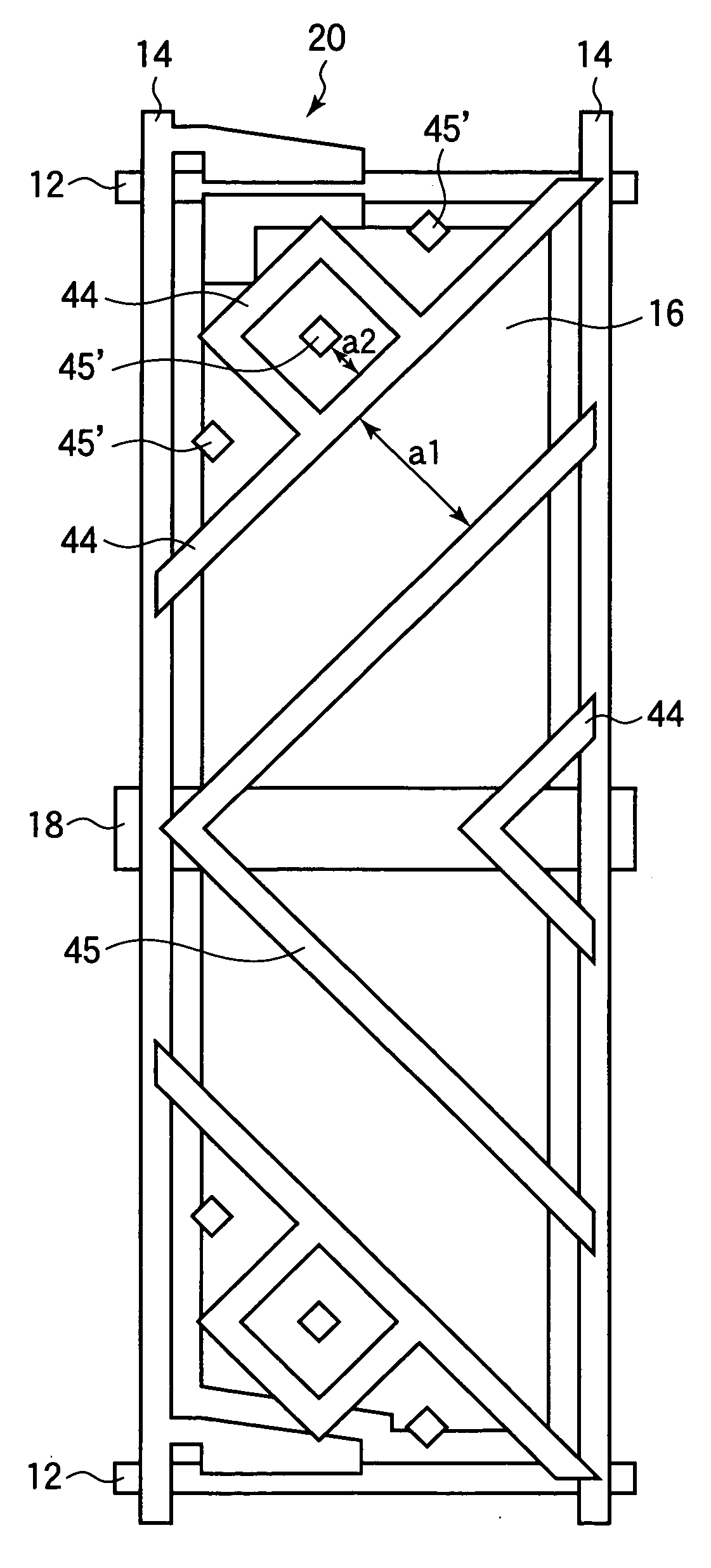
FIG. 10 shows Embodiment 1-2 of a liquid crystal display in the present mode for carrying out the invention. As shown in FIGS. 10, a point-like protrusion 45′ and a frame-like protrusion 44 disposed to surround the protrusion 45′ are formed in each of top left and bottom left areas of a pixel region. Intervals a2 between the protrusions 44 and 45′ in those areas are smaller than intervals a1 between the protrusions 44 and 45 in the rest of the pixel region. Thus, areas having different threshold voltages are both present in one pixel.

embodiment 1-3

<Embodiment 1-3>

FIG. 11 shows the disposition of alignment regulating structures in one pixel of a liquid crystal display in the present mode for carrying out the invention. As shown in FIG. 11, no linear protrusion as shown in FIG. 9 is formed on a TFT substrate 2, and slits 46 which are partial blanks in an electrode film of a pixel electrode 16 are formed instead. A plurality of slits 46′ having a space width smaller than that of the slits 46 are formed substantially orthogonally to directions in which the slits 46 extend, the series of protrusions 46′ being arranged in two extending directions of the slits 46 that converge toward a storage capacitor bus line 18 located in the middle of the pixel. An aligning direction can be more reliably regulated by providing the slits 46′.

Linear protrusions 44 are formed on an opposite substrate 4 which is provided opposite to the TFT substrate 2 and on which a color filter resin layer and a common electrode are formed, the linear prot...


PUM

PropertyMeasurementUnit
Angleaaaaaaaaaa
Lengthaaaaaaaaaa
Thicknessaaaaaaaaaa

Abstract

The invention relates to a liquid crystal display used as a display section of an electronic apparatus and a method of manufacturing the same, and it is aimed at providing a liquid crystal display which can achieve high viewing angle characteristics and a method of manufacturing the same. A configuration is employed which includes a pair of substrates provided opposite to each other, a liquid crystal sealed between the pair of substrates, protrusions formed on at least one of the pair of substrates for regulating the alignment of the liquid crystal, and a plurality of pixel regions having both of a first area in which the protrusions are disposed at first intervals a2 and which has a first threshold voltage for driving of the liquid crystal and a second area in which the protrusions are disposed at second intervals a2 smaller than the first intervals and which has a second threshold voltage lower than the first threshold voltage.

Description

BACKGROUND OF THE INVENTION 1. Field of the Invention The present invention relates to a liquid crystal display used as a display section of an electronic apparatus and a method of manufacturing the same, and more particularly to an MVA type liquid crystal display having high viewing angle characteristics and a method of manufacturing the same. 2. Description of the Related Art Recently, liquid crystal displays are widely used in various applications taking advantage of their features such as low profiles and light weights, low-voltage drivability and low power consumption. Further, some liquid crystal displays are available with display characteristics comparable to those of CRTs and are therefore being put in use as monitors and television receivers for which CRTs have been dominantly used. Among liquid crystal displays that are currently in practical use, MVA (Multi-domain Vertical Alignment) displays are one of types which exhibit high display characteristics comparable to ...

Claims


Application Information

Patent Timeline
IPC IPC(8): G02F1/1337G02F1/1333G02F1/1334G02F1/1343G02F1/1368
CPCG02F1/133371G02F1/133707G02F2001/134345G02F1/1393G02F2001/133757G02F1/133788G02F1/133757G02F1/134345E06B9/264E06B9/74E06B9/76E06B2009/2643E06B2009/6809
Inventor SASABAYASHI, TAKASHITAKEDA, ARIHIROINOUE, HIROYASUUEDA, KAZUYAKOIKE, YOSHIOTSUDA, HIDEAKITASAKA, YASUTOSHIYOSHIDA, HIDEFUMITASHIRO, KUNIHIROKAMADA, TSUYOSHINAKAMURA, KIMIAKI
Owner SHARP KK
Why Eureka
Try Eureka